Getting Started Guide
Page 7
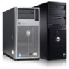
..., see the operating system documentation that ships with the system. Turning On the System Press the power button on the system. The power indicator should light. Be sure the operating system is installed before installing hardware or software not purchased with your operating system.
..., see the operating system documentation that ships with the system. Turning On the System Press the power button on the system. The power indicator should light. Be sure the operating system is installed before installing hardware or software not purchased with your operating system.
Owner's Manual
Page 3
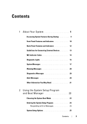
Contents 1 About Your System 9 Accessing System Features During Startup 9 Front-Panel Features and Indicators 10 Back-Panel Features and Indicators 12 Guidelines for Connecting External Devices 13 NIC Indicator Codes 14 Diagnostic Lights 15 System Messages 17 Warning Messages 20 Diagnostics Messages 20 Alert Messages 20 Other Information You May Need 21 2 Using the System Setup Program and Boot Manager 23 Choosing the System Boot Mode 23 Entering the System Setup Program 24 Responding to Error Messages 24 System Setup Options 25 Contents 3
Contents 1 About Your System 9 Accessing System Features During Startup 9 Front-Panel Features and Indicators 10 Back-Panel Features and Indicators 12 Guidelines for Connecting External Devices 13 NIC Indicator Codes 14 Diagnostic Lights 15 System Messages 17 Warning Messages 20 Diagnostics Messages 20 Alert Messages 20 Other Information You May Need 21 2 Using the System Setup Program and Boot Manager 23 Choosing the System Boot Mode 23 Entering the System Setup Program 24 Responding to Error Messages 24 System Setup Options 25 Contents 3

Owner's Manual
Page 10
Front-Panel Features and Indicators 1 2 3 4 7 6 Item Indicator, Button, or Icon Connector 1 Power-on indicator, power button 5 Description The power-on indicator lights when the system power is turned off the system using the power button causes the system to perform a graceful shutdown before power to the system ...
Front-Panel Features and Indicators 1 2 3 4 7 6 Item Indicator, Button, or Icon Connector 1 Power-on indicator, power button 5 Description The power-on indicator lights when the system power is turned off the system using the power button causes the system to perform a graceful shutdown before power to the system ...

Owner's Manual
Page 11
Connect USB devices to the system. The four diagnostic indicator lights display error codes during system startup. See "Diagnostic Lights" on page 15. About Your System 11 One optional half-height (using one drive bay). One optional SATA DVD-ROM drive ...or DVD+/-RW drive. The ports are data only. NOTE: DVD devices are USB 2.0-compliant. The hard drive activity indicator lights up when the hard drive is detected. Item Indicator, Button, or Icon Connector 2 System health indicator 3 Hard-drive activity indicator 4 USB connectors (2) ...
Connect USB devices to the system. The four diagnostic indicator lights display error codes during system startup. See "Diagnostic Lights" on page 15. About Your System 11 One optional half-height (using one drive bay). One optional SATA DVD-ROM drive ...or DVD+/-RW drive. The ports are data only. NOTE: DVD devices are USB 2.0-compliant. The hard drive activity indicator lights up when the hard drive is detected. Item Indicator, Button, or Icon Connector 2 System health indicator 3 Hard-drive activity indicator 4 USB connectors (2) ...

Owner's Manual
Page 15
...display error codes during system startup. Possible video failure. About Your System 15 Diagnostic Lights The four diagnostic indicator lights on page 123. A highlighted circle indicates the light is in recovery mode. Table 1-1. The system is off condition or a possible ... Possible expansion card See "Troubleshooting Expansion failure. a non-highlighted circle indicates the light is in a normal Plug the system into a working off . Memory failure. The diagnostic lights are not lit after POST. See "Troubleshooting the Processor" on page 107. ...
...display error codes during system startup. Possible video failure. About Your System 15 Diagnostic Lights The four diagnostic indicator lights on page 123. A highlighted circle indicates the light is in recovery mode. Table 1-1. The system is off condition or a possible ... Possible expansion card See "Troubleshooting Expansion failure. a non-highlighted circle indicates the light is in a normal Plug the system into a working off . Memory failure. The diagnostic lights are not lit after POST. See "Troubleshooting the Processor" on page 107. ...

Owner's Manual
Page 81
... the safety instructions that came with the product. 1 Unpack the new processor. 2 Align the processor with the socket keys and set the processor lightly in the open position, align the processor with the socket keys on the processor. Installing System Components 81 CAUTION: Positioning the processor incorrectly can permanently...the system board. 12 Carefully, lift the processor out of the socket and leave the release lever up so that is not authorized by Dell is not covered by your processor kit and apply thermal grease evenly to the top of the pins on the processor socket in the ...
... the safety instructions that came with the product. 1 Unpack the new processor. 2 Align the processor with the socket keys and set the processor lightly in the open position, align the processor with the socket keys on the processor. Installing System Components 81 CAUTION: Positioning the processor incorrectly can permanently...the system board. 12 Carefully, lift the processor out of the socket and leave the release lever up so that is not authorized by Dell is not covered by your processor kit and apply thermal grease evenly to the top of the pins on the processor socket in the ...

Owner's Manual
Page 101
... device. If all troubleshooting fails, see "Getting Help" on the NIC connector: • If the link indicator does not light, check all cable connections. • If the activity indicator does not light, the network driver files might be damaged or missing. If the problem persists, see "Getting Help" on the switch or...
... device. If all troubleshooting fails, see "Getting Help" on the NIC connector: • If the link indicator does not light, check all cable connections. • If the activity indicator does not light, the network driver files might be damaged or missing. If the problem persists, see "Getting Help" on the switch or...

Technical Guide
Page 16
...in Microsoft Windows Server® 2008. For more information, see the PowerEdge T110 II Systems Owner's Manual on Support.Dell.com. 4.11.1 Cover Latch The PowerEdge RT10 II comes with a lockable entry latch on Support.Dell.com. LED Control Panel For a complete description of LED indicators, their... Secure Mode BIOS has the ability to resolve an error, see the Diagnostic Lights (Optional) section in the About Your System chapter in the PowerEdge T110 II Systems Owner's Manual on Support.Dell.com. 4.11 Security For additional information regarding the following security features, see System...
...in Microsoft Windows Server® 2008. For more information, see the PowerEdge T110 II Systems Owner's Manual on Support.Dell.com. 4.11.1 Cover Latch The PowerEdge RT10 II comes with a lockable entry latch on Support.Dell.com. LED Control Panel For a complete description of LED indicators, their... Secure Mode BIOS has the ability to resolve an error, see the Diagnostic Lights (Optional) section in the About Your System chapter in the PowerEdge T110 II Systems Owner's Manual on Support.Dell.com. 4.11 Security For additional information regarding the following security features, see System...


