User Manual
Page 7
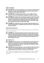
... specific caution statements and procedures. Failure to ensure that installation of equipment with any other rack. • Before installing your system and working environment from the bottom up, and load the heaviest items first. • Do not overload the AC power supply branch circuit that shipped with all front and side stabilizers. Rack Installation Instructions This installation guide provides instructions for trained service technicians installing a rack enclosure. Dell...
... specific caution statements and procedures. Failure to ensure that installation of equipment with any other rack. • Before installing your system and working environment from the bottom up, and load the heaviest items first. • Do not overload the AC power supply branch circuit that shipped with all front and side stabilizers. Rack Installation Instructions This installation guide provides instructions for trained service technicians installing a rack enclosure. Dell...

User Manual
Page 9
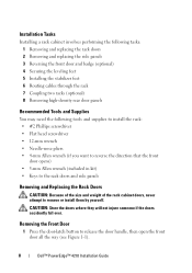
... injury under certain circumstances. WARNING: After installing systems in the rack. Installation Tasks Installing a rack cabinet involves the following tasks: 1 Removing and replacing the rack doors 2 Removing and replacing the side panels 3 Reversing the front door and badge (optional) 4 Securing the leveling feet 5 Installing the stabilizer feet 6 Adjusting the rack posts (optional) 7 Routing cables through the rack 8 Coupling two racks (optional) Recommended Tools and Supplies You may need the...
... injury under certain circumstances. WARNING: After installing systems in the rack. Installation Tasks Installing a rack cabinet involves the following tasks: 1 Removing and replacing the rack doors 2 Removing and replacing the side panels 3 Reversing the front door and badge (optional) 4 Securing the leveling feet 5 Installing the stabilizer feet 6 Adjusting the rack posts (optional) 7 Routing cables through the rack 8 Coupling two racks (optional) Recommended Tools and Supplies You may need the...

User Manual
Page 14
... side panels in a rack, having the sides open makes it easier to install slide assemblies and support rails and to its cosmetic coating. Laying the door flat with the panel's outer surface facing upward to help prevent damage to reverse the direction that the front door opens. NOTE: Although removing the side panels is necessary before running systems in a safe location with...
... side panels in a rack, having the sides open makes it easier to install slide assemblies and support rails and to its cosmetic coating. Laying the door flat with the panel's outer surface facing upward to help prevent damage to reverse the direction that the front door opens. NOTE: Although removing the side panels is necessary before running systems in a safe location with...

User Manual
Page 33
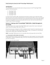
...) 3 2 plunger (2 per bar) Installation Guide 31 Figure 1-18. Removing and Installing the Back Door Stabilizer Bars The top and bottom bars used to stabilize the back doors can be removed, making it easier to route cables through the top and bottom of the rack. 1 Open the back doors. 2 Pull and hold... the plungers on each side of the bar, and pull the bar up and away from the rack (see Figure 1-18). 3 After routing your cables, replace...
...) 3 2 plunger (2 per bar) Installation Guide 31 Figure 1-18. Removing and Installing the Back Door Stabilizer Bars The top and bottom bars used to stabilize the back doors can be removed, making it easier to route cables through the top and bottom of the rack. 1 Open the back doors. 2 Pull and hold... the plungers on each side of the bar, and pull the bar up and away from the rack (see Figure 1-18). 3 After routing your cables, replace...
Dell PowerEdge 2420 Rack Installation Guide
Page 7
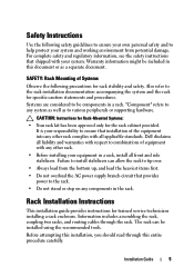
... overload the AC power supply branch circuit that shipped with your system. Failure to install stabilizers can be installed using the recommended tools. Information includes assembling the rack and routing cables through the rack. "Component" refers to any components in a rack, install all applicable standards. Installation Guide 5 Systems are considered to various peripherals or supporting hardware. Safety Instructions Use the following precautions for the rack cabinet provided. Warranty...
... overload the AC power supply branch circuit that shipped with your system. Failure to install stabilizers can be installed using the recommended tools. Information includes assembling the rack and routing cables through the rack. "Component" refers to any components in a rack, install all applicable standards. Installation Guide 5 Systems are considered to various peripherals or supporting hardware. Safety Instructions Use the following precautions for the rack cabinet provided. Warranty...

Dell PowerEdge 2420 Rack Installation Guide
Page 28
... from the rack (see Figure 1-16). 3 After routing your cables, replace the bars by aligning the tabs on the bars with the corresponding holes in the rack and pushing in and down until the plungers lock into place. Figure 1-16. Removing and Installing the Back Door Stabilizer Bars 1 1 back door stabilizer bar (2) 2 2 plungers (2 per bar) 26 Installation Guide
... from the rack (see Figure 1-16). 3 After routing your cables, replace the bars by aligning the tabs on the bars with the corresponding holes in the rack and pushing in and down until the plungers lock into place. Figure 1-16. Removing and Installing the Back Door Stabilizer Bars 1 1 back door stabilizer bar (2) 2 2 plungers (2 per bar) 26 Installation Guide
User Manual
Page 7
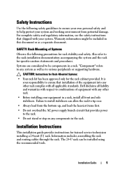
... system. Systems are intended to be included in this document or as a component for use in a rack could cause the rack to various peripherals or supporting hardware. Safety Instructions Use the following precautions for specific caution statements and procedures. Therefore, always install the stabilizer(s) before installing systems in a Dell rack cabinet using the customer rack kit. The weight of Systems Observe the following safety guidelines to ensure...
... system. Systems are intended to be included in this document or as a component for use in a rack could cause the rack to various peripherals or supporting hardware. Safety Instructions Use the following precautions for specific caution statements and procedures. Therefore, always install the stabilizer(s) before installing systems in a Dell rack cabinet using the customer rack kit. The weight of Systems Observe the following safety guidelines to ensure...
User Manual
Page 9
... in this document to tip over when a system or other component is pulled out of cabinet control may be very large and heavy, and proper preparation and planning are installed high up in the rack. Use extreme caution while moving the rack cabinet. Rack Stabilizer Feet CAUTION: Installing systems in bodily injury under certain circumstances. Dell™ PowerEdge™ 4210 Installation Guide 7 The...
... in this document to tip over when a system or other component is pulled out of cabinet control may be very large and heavy, and proper preparation and planning are installed high up in the rack. Use extreme caution while moving the rack cabinet. Rack Stabilizer Feet CAUTION: Installing systems in bodily injury under certain circumstances. Dell™ PowerEdge™ 4210 Installation Guide 7 The...
User Manual
Page 10
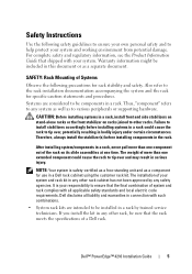
... reverse the direction that the front door opens) • 5-mm Allen wrench (included in kit) • Keys to the rack doors and side panels Removing and Replacing the Rack Doors CAUTION: Because of the size and weight of the rack cabinet doors, never attempt to release the door handle, then open the front door all the way (see Figure 1-1). 8 Dell™ PowerEdge™ 4210 Installation Guide
... reverse the direction that the front door opens) • 5-mm Allen wrench (included in kit) • Keys to the rack doors and side panels Removing and Replacing the Rack Doors CAUTION: Because of the size and weight of the rack cabinet doors, never attempt to release the door handle, then open the front door all the way (see Figure 1-1). 8 Dell™ PowerEdge™ 4210 Installation Guide
Cabling PowerEdge R815
Page 4
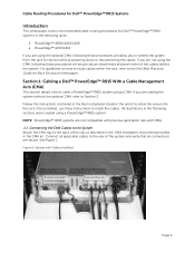
... 1: Cabling a Dell™ PowerEdge™ R815 With a Cable Management Arm (CMA) This section details how to extend the system from the rack for Rack Enclosure white paper. NOTE: PowerEdge™ R815 systems are secure. Figure 1: System with previous generation rails and CMAs. 1.1 Connecting the CMA Cables to the System Attach the CMA tray to install the server into the rack. Follow the instructions contained in the Rack Installation Guide...
... 1: Cabling a Dell™ PowerEdge™ R815 With a Cable Management Arm (CMA) This section details how to extend the system from the rack for Rack Enclosure white paper. NOTE: PowerEdge™ R815 systems are secure. Figure 1: System with previous generation rails and CMAs. 1.1 Connecting the CMA Cables to the System Attach the CMA tray to install the server into the rack. Follow the instructions contained in the Rack Installation Guide...
Cabling PowerEdge R810
Page 4
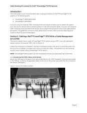
.... Connect all applicable cables to the rear of the rails as described in the CMA Installation Instructions provided in the rail kit to install the server into the rack. If you are secure. See Figure 1. Cable Routing Procedures for Dell™ PowerEdge™ R810 Systems Introduction This white paper covers recommended cable routing procedures for Dell™ PowerEdge™ R810 systems in the following racks: • PowerEdge™ 4210 • PowerEdge™...
.... Connect all applicable cables to the rear of the rails as described in the CMA Installation Instructions provided in the rail kit to install the server into the rack. If you are secure. See Figure 1. Cable Routing Procedures for Dell™ PowerEdge™ R810 Systems Introduction This white paper covers recommended cable routing procedures for Dell™ PowerEdge™ R810 systems in the following racks: • PowerEdge™ 4210 • PowerEdge™...
Cabling PowerEdge R715
Page 4
... 2 Connect all applicable cables to the rear of the rails as described in the CMA Installation Instructions provided in the CMA kit. If you are not using the CMA, following these procedures will allow you to extend the system from the rack for Rack Enclosure white paper. Follow the instructions contained in the Rack Installation Guide in the rail kit to install the cables. Section 1: Cabling a Dell™ PowerEdge™ R715 With a Cable Management...
... 2 Connect all applicable cables to the rear of the rails as described in the CMA Installation Instructions provided in the CMA kit. If you are not using the CMA, following these procedures will allow you to extend the system from the rack for Rack Enclosure white paper. Follow the instructions contained in the Rack Installation Guide in the rail kit to install the cables. Section 1: Cabling a Dell™ PowerEdge™ R715 With a Cable Management...

Cabling PowerEdge R710
Page 3
...Figure 2: Routing Power Cables Through the Strain Reliefs 3 2.3 Routing the Cables Through the CMA...3 Figure 3: Routing the Cables Through the CMA 4 Figure 4: Completed Left Side Mounted CMA Installation 5 Figure 5: Completed Right Side Mounted CMA Installation 5 Cabling a PowerEdge R710 Without a CMA ...5 3.1 Routing the Cables ...5 Figure 6: Cable Routing Without a CMA...6 Replacing a Power Supply on a PowerEdge R710 with CMA 6 Figure 7: Replacing Outer Power Supply ...7 Cabling a PowerEdge R710 Installed in Static Rails 7 Figure 8: Cabling a System Installed in Static Rails 7 Page 1
...Figure 2: Routing Power Cables Through the Strain Reliefs 3 2.3 Routing the Cables Through the CMA...3 Figure 3: Routing the Cables Through the CMA 4 Figure 4: Completed Left Side Mounted CMA Installation 5 Figure 5: Completed Right Side Mounted CMA Installation 5 Cabling a PowerEdge R710 Without a CMA ...5 3.1 Routing the Cables ...5 Figure 6: Cable Routing Without a CMA...6 Replacing a Power Supply on a PowerEdge R710 with CMA 6 Figure 7: Replacing Outer Power Supply ...7 Cabling a PowerEdge R710 Installed in Static Rails 7 Figure 8: Cabling a System Installed in Static Rails 7 Page 1
Cabling PowerEdge R710
Page 4
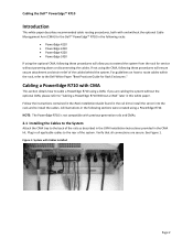
... extend the system from the rack for service without powering down or disconnecting the cables. If you to the back of the cables behind the system. All illustrations in all connections are cabling the system without the optional Cable Management Arm (CMA) for Rack Enclosures." Follow the instructions contained in the Rack Installation Guide found in this white paper. Cabling the Dell™ PowerEdge™ R710 Introduction This...
... extend the system from the rack for service without powering down or disconnecting the cables. If you to the back of the cables behind the system. All illustrations in all connections are cabling the system without the optional Cable Management Arm (CMA) for Rack Enclosures." Follow the instructions contained in the Rack Installation Guide found in this white paper. Cabling the Dell™ PowerEdge™ R710 Introduction This...
Cabling PowerEdge R710
Page 8
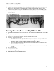
... power cables secured to the right CMA bracket and data cables secured to either the left rail or right rail CMA attachment brackets as described in Figure 7. Swing the CMA into the service position. 3. While supporting the CMA with one hand, remove and replace the power supply with CMA 1. Page 6 Using the hook and loop straps supplied with the CMA kit. 2. Remove the tray from the power supply...
... power cables secured to the right CMA bracket and data cables secured to either the left rail or right rail CMA attachment brackets as described in Figure 7. Swing the CMA into the service position. 3. While supporting the CMA with one hand, remove and replace the power supply with CMA 1. Page 6 Using the hook and loop straps supplied with the CMA kit. 2. Remove the tray from the power supply...

Cabling PowerEdge R610
Page 3
... Dongle to the CMA Basket 4 Figure 5: Completed Left Side Mounted CMA Installation 5 Figure 6: Completed Right Side Mounted CMA Installation 5 Cabling a PowerEdge R610 without a CMA ...6 3.1 Routing the Cables ...6 Figure 7: Cable Routing Without a CMA 6 3.1 Removing the CMA Brackets for Shallow Racks 6 Figure 8: Removing the CMA Brackets for Shallow Racks 6 Replacing a Power Supply on a PowerEdge R610 with CMA 7 Figure 9: Replacing Outer Power Supply 7 Cabling a PowerEdge R610 Installed in Static Rails 8 Figure 10: Cabling a System Installed in Static Rails 8 Page 1
... Dongle to the CMA Basket 4 Figure 5: Completed Left Side Mounted CMA Installation 5 Figure 6: Completed Right Side Mounted CMA Installation 5 Cabling a PowerEdge R610 without a CMA ...6 3.1 Routing the Cables ...6 Figure 7: Cable Routing Without a CMA 6 3.1 Removing the CMA Brackets for Shallow Racks 6 Figure 8: Removing the CMA Brackets for Shallow Racks 6 Replacing a Power Supply on a PowerEdge R610 with CMA 7 Figure 9: Replacing Outer Power Supply 7 Cabling a PowerEdge R610 Installed in Static Rails 8 Figure 10: Cabling a System Installed in Static Rails 8 Page 1
Cabling PowerEdge R610
Page 9
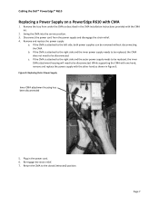
... will need to be disconnected. While supporting the CMA with one hand, remove and replace the power supply with CMA 1. Re‐engage the strain relief. 7. Page 7 Cabling the Dell™ PowerEdge™ R610 Replacing a Power Supply on a PowerEdge R610 with the other hand as described in the CMA Installation Instructions provided with the CMA kit. 2. Remove the tray from the power supply and disengage the strain relief...
... will need to be disconnected. While supporting the CMA with one hand, remove and replace the power supply with CMA 1. Re‐engage the strain relief. 7. Page 7 Cabling the Dell™ PowerEdge™ R610 Replacing a Power Supply on a PowerEdge R610 with the other hand as described in the CMA Installation Instructions provided with the CMA kit. 2. Remove the tray from the power supply and disengage the strain relief...
Best Practices Guide for Rack Enclosures
Page 4
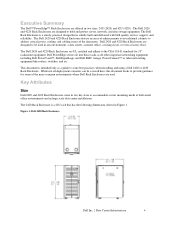
...). This document is solidly built and delivered with Dell quality service, support, and reliability. The 2420 Rack Enclosure is a 24U rack that is intended only as do other important networking equipment including Dell PowerVault™, Dell EqualLogic and Dell EMC storage, PowerConnect™ or other networking equipment like routers, switches, and etc. Dell 2420 and 4220 Rack Enclosures are offered in Figure 1. Dell PowerEdge servers fit into these racks as a guide to...
...). This document is solidly built and delivered with Dell quality service, support, and reliability. The 2420 Rack Enclosure is a 24U rack that is intended only as do other important networking equipment including Dell PowerVault™, Dell EqualLogic and Dell EMC storage, PowerConnect™ or other networking equipment like routers, switches, and etc. Dell 2420 and 4220 Rack Enclosures are offered in Figure 1. Dell PowerEdge servers fit into these racks as a guide to...
Best Practices Guide for Rack Enclosures
Page 5
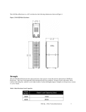
... 2: Dell 4220 Rack Enclosure Strength The new Dell Rack Enclosures have been upgraded with redesigned frame base members, stronger corner weld joints, better reinforced leveling feet, and new castor wheels made of nylon with higher impact strength over the previous version of Dell Rack Enclosures. They have increased static load capacity versus the previous generation of castor wheels. Rack Enclosure Load Capacities Rack Model 2420...
... 2: Dell 4220 Rack Enclosure Strength The new Dell Rack Enclosures have been upgraded with redesigned frame base members, stronger corner weld joints, better reinforced leveling feet, and new castor wheels made of nylon with higher impact strength over the previous version of Dell Rack Enclosures. They have increased static load capacity versus the previous generation of castor wheels. Rack Enclosure Load Capacities Rack Model 2420...
Best Practices Guide for Rack Enclosures
Page 8
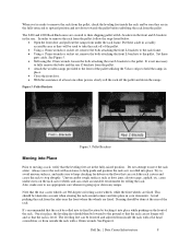
...avoid uneven surfaces, and make sure to remove the rack from the pallet: follow the steps listed below. • Open the front door and pull out the ramps from the sides near the front where the wheels are fixed. Avoid pushing the rack from under the rack frame. See Figure 6. It is ...castor wheels, while the front wheels are in the rear. Put these parts aside. Uneven and/or rough surfaces such as it into place. Set these aside in a readily accessible area as they are fixed. Steering should be used to take the rack off the pallet and down towards the pallet before ...
...avoid uneven surfaces, and make sure to remove the rack from the pallet: follow the steps listed below. • Open the front door and pull out the ramps from the sides near the front where the wheels are fixed. Avoid pushing the rack from under the rack frame. See Figure 6. It is ...castor wheels, while the front wheels are in the rear. Put these parts aside. Uneven and/or rough surfaces such as it into place. Set these aside in a readily accessible area as they are fixed. Steering should be used to take the rack off the pallet and down towards the pallet before ...

