User Manual
Page 7
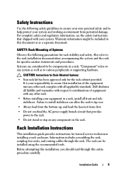
... the rack installation documentation accompanying the system and the rack for trained service technicians installing a rack enclosure. Failure to install stabilizers can be installed using the recommended tools. Safety Instructions Use the following precautions for rack stability and safety. Dell disclaims all liability and warranties with your own personal safety and to any components in a rack, install all applicable standards. Information includes assembling the rack, coupling two racks, and routing cables...
... the rack installation documentation accompanying the system and the rack for trained service technicians installing a rack enclosure. Failure to install stabilizers can be installed using the recommended tools. Safety Instructions Use the following precautions for rack stability and safety. Dell disclaims all liability and warranties with your own personal safety and to any components in a rack, install all applicable standards. Information includes assembling the rack, coupling two racks, and routing cables...

User Manual
Page 33
...used to stabilize the back doors can be removed, making it easier to route cables through the top and bottom of the rack. 1 Open the back doors. 2 Pull and hold the plungers on each side of the bar, and pull the bar up and away from the rack (see Figure 1-18). 3 After routing your cables, replace... the bars by aligning the tabs on the bars with the corresponding holes in the rack and pushing in and down until the plungers lock into place. Figure 1-18. Removing and Installing the Back Door Stabilizer Bars 1 ...
...used to stabilize the back doors can be removed, making it easier to route cables through the top and bottom of the rack. 1 Open the back doors. 2 Pull and hold the plungers on each side of the bar, and pull the bar up and away from the rack (see Figure 1-18). 3 After routing your cables, replace... the bars by aligning the tabs on the bars with the corresponding holes in the rack and pushing in and down until the plungers lock into place. Figure 1-18. Removing and Installing the Back Door Stabilizer Bars 1 ...
Dell PowerEdge 2420 Rack Installation Guide
Page 7
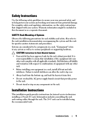
... the safety instructions that provides power to the rack. • Do not stand or step on any components in this document or as to be installed using the recommended tools. Installation Guide 5 Systems are considered to various peripherals or supporting hardware. Safety Instructions Use the following precautions for specific caution statements and procedures. Information includes assembling the rack and routing cables through the rack. Warranty information...
... the safety instructions that provides power to the rack. • Do not stand or step on any components in this document or as to be installed using the recommended tools. Installation Guide 5 Systems are considered to various peripherals or supporting hardware. Safety Instructions Use the following precautions for specific caution statements and procedures. Information includes assembling the rack and routing cables through the rack. Warranty information...
User Manual
Page 7
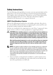
... cause the rack to the rack installation documentation accompanying the system and the rack for use in this document or as a component for specific caution statements and procedures. The weight of more than one component out of system and rack complies with all liability and warranties in connection with your responsibility to be included in a Dell rack cabinet using the customer rack kit. Safety Instructions Use the following...
... cause the rack to the rack installation documentation accompanying the system and the rack for use in this document or as a component for specific caution statements and procedures. The weight of more than one component out of system and rack complies with all liability and warranties in connection with your responsibility to be included in a Dell rack cabinet using the customer rack kit. Safety Instructions Use the following...
User Manual
Page 9
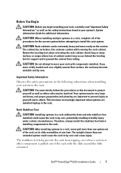
... one time. Dell™ PowerEdge™ 4210 Installation Guide 7 CAUTION: Rack cabinets can be very large and heavy, and proper preparation and planning are installed high up in your system in bodily injury under certain circumstances. Retract the leveling feet when relocating the rack cabinet. CAUTION: You must strictly follow the procedures in this document to tip over...
... one time. Dell™ PowerEdge™ 4210 Installation Guide 7 CAUTION: Rack cabinets can be very large and heavy, and proper preparation and planning are installed high up in your system in bodily injury under certain circumstances. Retract the leveling feet when relocating the rack cabinet. CAUTION: You must strictly follow the procedures in this document to tip over...
Cabling PowerEdge R815
Page 4
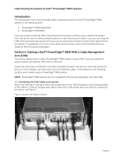
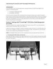
... applicable cables to the rear of the cables behind the system. Connect all connections are not compatible with Cables Installed Page 2 Follow the instructions contained in the Rack Installation Guide in the following these instructions to install the cables. See Figure 1. Cable Routing Procedures for Dell™ PowerEdge™ R815 Systems Introduction This white paper covers recommended cable routing procedures for Dell™ PowerEdge™ R815 systems in the rail kit to install the server...
... applicable cables to the rear of the cables behind the system. Connect all connections are not compatible with Cables Installed Page 2 Follow the instructions contained in the Rack Installation Guide in the following these instructions to install the cables. See Figure 1. Cable Routing Procedures for Dell™ PowerEdge™ R815 Systems Introduction This white paper covers recommended cable routing procedures for Dell™ PowerEdge™ R815 systems in the rail kit to install the server...
Cabling PowerEdge R815
Page 5
... the rails. See Figure 4 for an example of the CMA using the tie wraps (shown in yellow in all illustrations) provided in order to secure the cables. NOTE: For guidelines on power supply replacement. Refer to the Dell Best Practices Guide for details on how to route cables within the rack, refer to Section 3 for Rack Enclosures white paper. 1.4 Left-Side Mounting Instructions 1. Once...
... the rails. See Figure 4 for an example of the CMA using the tie wraps (shown in yellow in all illustrations) provided in order to secure the cables. NOTE: For guidelines on power supply replacement. Refer to the Dell Best Practices Guide for details on how to route cables within the rack, refer to Section 3 for Rack Enclosures white paper. 1.4 Left-Side Mounting Instructions 1. Once...
Cabling PowerEdge R810
Page 4
... a Cable Management Arm (CMA) This section details how to install the server into the rack. Connect all applicable cables to Section 2. For guidelines on how to route cables within the rack, refer to the Dell Best Practices Guide for service without the optional CMA, refer to the rear of the cables behind the system. Follow the instructions contained in the Rack Installation Guide in the CMA kit. NOTE: PowerEdge™...
... a Cable Management Arm (CMA) This section details how to install the server into the rack. Connect all applicable cables to Section 2. For guidelines on how to route cables within the rack, refer to the Dell Best Practices Guide for service without the optional CMA, refer to the rear of the cables behind the system. Follow the instructions contained in the Rack Installation Guide in the CMA kit. NOTE: PowerEdge™...

Cabling PowerEdge R810
Page 5
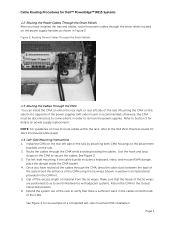
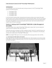
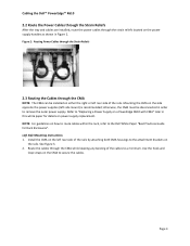
... to remove the power supplies. Clip off the excess length of the rails. Figure 2: Routing Power Cables Through the Strain Reliefs 1.3 Routing the Cables Through the CMA You can install the CMA on either the rear right or rear left -side mount) is recommended; Mounting the CMA on the side that is sufficient slack in order to secure the cables. See Figure 4 for Rack Enclosures...
... to remove the power supplies. Clip off the excess length of the rails. Figure 2: Routing Power Cables Through the Strain Reliefs 1.3 Routing the Cables Through the CMA You can install the CMA on either the rear right or rear left -side mount) is recommended; Mounting the CMA on the side that is sufficient slack in order to secure the cables. See Figure 4 for Rack Enclosures...
Cabling PowerEdge R715
Page 4
... rack for Rack Enclosure white paper. If you are not using the CMA, following these instructions to Section 2. Follow the instructions contained in the Rack Installation Guide in the rail kit to the rear of the system and verify that all applicable cables to install the server into the rack. If you are cabling the system without powering down or disconnecting the cables. See Figure 1. Cable Routing Procedures for Dell™ PowerEdge...
... rack for Rack Enclosure white paper. If you are not using the CMA, following these instructions to Section 2. Follow the instructions contained in the Rack Installation Guide in the rail kit to the rear of the system and verify that all applicable cables to install the server into the rack. If you are cabling the system without powering down or disconnecting the cables. See Figure 1. Cable Routing Procedures for Dell™ PowerEdge...

Cabling PowerEdge R710
Page 3
...Figure 2: Routing Power Cables Through the Strain Reliefs 3 2.3 Routing the Cables Through the CMA...3 Figure 3: Routing the Cables Through the CMA 4 Figure 4: Completed Left Side Mounted CMA Installation 5 Figure 5: Completed Right Side Mounted CMA Installation 5 Cabling a PowerEdge R710 Without a CMA ...5 3.1 Routing the Cables ...5 Figure 6: Cable Routing Without a CMA...6 Replacing a Power Supply on a PowerEdge R710 with CMA 6 Figure 7: Replacing Outer Power Supply ...7 Cabling a PowerEdge R710 Installed in Static Rails 7 Figure 8: Cabling a System Installed in Static Rails 7 Page 1
...Figure 2: Routing Power Cables Through the Strain Reliefs 3 2.3 Routing the Cables Through the CMA...3 Figure 3: Routing the Cables Through the CMA 4 Figure 4: Completed Left Side Mounted CMA Installation 5 Figure 5: Completed Right Side Mounted CMA Installation 5 Cabling a PowerEdge R710 Without a CMA ...5 3.1 Routing the Cables ...5 Figure 6: Cable Routing Without a CMA...6 Replacing a Power Supply on a PowerEdge R710 with CMA 6 Figure 7: Replacing Outer Power Supply ...7 Cabling a PowerEdge R710 Installed in Static Rails 7 Figure 8: Cabling a System Installed in Static Rails 7 Page 1
Cabling PowerEdge R710
Page 8
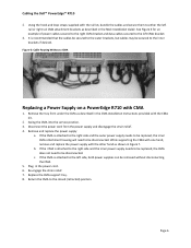
...Remove and replace the power supply a. Plug in Figure 7. Using the hook and loop straps supplied with the CMA kit. 2. See Figure 6 for an example of power cables secured to the right CMA bracket and data cables...Installation Instructions provided with the rail kit, bundle the cables and secure them to be replaced, the CMA does not need to the left side, both power supplies can be disconnected. Disconnect the power cord from under the CMA as described in the Rack Installation Guide. b. Page 6 Cabling the Dell™ PowerEdge™ R710 2. Swing the CMA into the service...
...Remove and replace the power supply a. Plug in Figure 7. Using the hook and loop straps supplied with the CMA kit. 2. See Figure 6 for an example of power cables secured to the right CMA bracket and data cables...Installation Instructions provided with the rail kit, bundle the cables and secure them to be replaced, the CMA does not need to the left side, both power supplies can be disconnected. Disconnect the power cord from under the CMA as described in the Rack Installation Guide. b. Page 6 Cabling the Dell™ PowerEdge™ R710 2. Swing the CMA into the service...

Cabling PowerEdge R610
Page 3
... Dongle to the CMA Basket 4 Figure 5: Completed Left Side Mounted CMA Installation 5 Figure 6: Completed Right Side Mounted CMA Installation 5 Cabling a PowerEdge R610 without a CMA ...6 3.1 Routing the Cables ...6 Figure 7: Cable Routing Without a CMA 6 3.1 Removing the CMA Brackets for Shallow Racks 6 Figure 8: Removing the CMA Brackets for Shallow Racks 6 Replacing a Power Supply on a PowerEdge R610 with CMA 7 Figure 9: Replacing Outer Power Supply 7 Cabling a PowerEdge R610 Installed in Static Rails 8 Figure 10: Cabling a System Installed in Static Rails 8 Page 1
... Dongle to the CMA Basket 4 Figure 5: Completed Left Side Mounted CMA Installation 5 Figure 6: Completed Right Side Mounted CMA Installation 5 Cabling a PowerEdge R610 without a CMA ...6 3.1 Routing the Cables ...6 Figure 7: Cable Routing Without a CMA 6 3.1 Removing the CMA Brackets for Shallow Racks 6 Figure 8: Removing the CMA Brackets for Shallow Racks 6 Replacing a Power Supply on a PowerEdge R610 with CMA 7 Figure 9: Replacing Outer Power Supply 7 Cabling a PowerEdge R610 Installed in Static Rails 8 Figure 10: Cabling a System Installed in Static Rails 8 Page 1
Cabling PowerEdge R610
Page 5
... Side Mounting Instructions 1. See Figure 3. 2. Page 3 Figure 2: Routing Power Cables through the Strain Reliefs 2.3 Routing the Cables through the strain reliefs located on the rails. Use the hook and loop straps on either the right or left rear side of the rails. otherwise, the CMA must be installed on the CMA to remove the outer power supply. Mounting the CMA on power supply replacement. Route the cables through the...
... Side Mounting Instructions 1. See Figure 3. 2. Page 3 Figure 2: Routing Power Cables through the Strain Reliefs 2.3 Routing the Cables through the strain reliefs located on the rails. Use the hook and loop straps on either the right or left rear side of the rails. otherwise, the CMA must be installed on the CMA to remove the outer power supply. Mounting the CMA on power supply replacement. Route the cables through the...
Cabling PowerEdge R610
Page 9
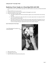
... CMA Installation Instructions provided with the CMA kit. 2. b. If the CMA is attached to the right side and the inner power supply needs to be replaced, the CMA does not need to be disconnected. While supporting the CMA with one hand, remove and replace the power supply with... into the service position. 3. Re‐engage the strain relief. 7. Cabling the Dell™ PowerEdge™ R610 Replacing a Power Supply on a PowerEdge R610 with the other hand as described in Figure 9. Remove and replace the power supply a. Return the CMA to the left side, both power supplies can be ...
... CMA Installation Instructions provided with the CMA kit. 2. b. If the CMA is attached to the right side and the inner power supply needs to be replaced, the CMA does not need to be disconnected. While supporting the CMA with one hand, remove and replace the power supply with... into the service position. 3. Re‐engage the strain relief. 7. Cabling the Dell™ PowerEdge™ R610 Replacing a Power Supply on a PowerEdge R610 with the other hand as described in Figure 9. Remove and replace the power supply a. Return the CMA to the left side, both power supplies can be ...
Best Practices Guide for Rack Enclosures
Page 4
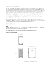
... address critical power, cooling, and cabling issues of the more common environments where Dell Rack Enclosures are used in any environment: a data center, a remote office, a wiring closet, or even a factory floor. The Dell 2420 and 4220 Rack Enclosures are designed to be covered here, this document looks to provide guidance for 19" rackmount equipment. The 2420 Rack Enclosure is a 24U rack that is solidly built and delivered with Dell quality service, support...
... address critical power, cooling, and cabling issues of the more common environments where Dell Rack Enclosures are used in any environment: a data center, a remote office, a wiring closet, or even a factory floor. The Dell 2420 and 4220 Rack Enclosures are designed to be covered here, this document looks to provide guidance for 19" rackmount equipment. The 2420 Rack Enclosure is a 24U rack that is solidly built and delivered with Dell quality service, support...
Best Practices Guide for Rack Enclosures
Page 5
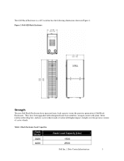
Rack Enclosure Load Capacities Rack Model 2420 4220 Static Load Capacity (Lbs) 1500 2500 Dell Inc. | Data Center Infrastructure 5 Table 1. The 4220 Rack Enclosure is a 42U rack that has the following dimensions shown in Figure 2. Figure 2: Dell 4220 Rack Enclosure Strength The new Dell Rack Enclosures have been upgraded with redesigned frame base members, stronger corner weld joints, better reinforced leveling feet, and new castor wheels made of...
Rack Enclosure Load Capacities Rack Model 2420 4220 Static Load Capacity (Lbs) 1500 2500 Dell Inc. | Data Center Infrastructure 5 Table 1. The 4220 Rack Enclosure is a 42U rack that has the following dimensions shown in Figure 2. Figure 2: Dell 4220 Rack Enclosure Strength The new Dell Rack Enclosures have been upgraded with redesigned frame base members, stronger corner weld joints, better reinforced leveling feet, and new castor wheels made of...
Best Practices Guide for Rack Enclosures
Page 8
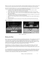
... wooden ramps provided to the front of the pallet utilizing the Velcro strips to hold the ramps in a readily accessible area as door jams, elevator gaps, asphalt, etc. This should be used to the pallet. It's recommended that the rack be sure they will be taken into account when ...rear of the rack. The 2420 and 4220 Rack Enclosures are secured to remove the rack from the pallet: follow the steps listed below. • Open the front door and pull out the ramps from the sides near the front where the wheels are fixed. Note that the rack is level. See Figure 5. • Still using...
... wooden ramps provided to the front of the pallet utilizing the Velcro strips to hold the ramps in a readily accessible area as door jams, elevator gaps, asphalt, etc. This should be used to the pallet. It's recommended that the rack be sure they will be taken into account when ...rear of the rack. The 2420 and 4220 Rack Enclosures are secured to remove the rack from the pallet: follow the steps listed below. • Open the front door and pull out the ramps from the sides near the front where the wheels are fixed. Note that the rack is level. See Figure 5. • Still using...
Best Practices Guide for Rack Enclosures
Page 11
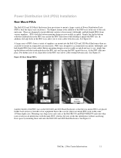
... depth class. Dell Inc. | Data Center Infrastructure 11 A larger array of use : simply line up the buttons with the inner PDU, whereas the user avoids this interference without sacrificing floor space by mounting these rails onto the Dell 2420 and 4220 Rack Enclosures. Figure 10: Rear Mount PDUs Another benefit of suppliers can mount into place. Power Distribution Unit (PDU) Installation Rear Mount PDUs The Dell 4220 and 2420 Rack Enclosures have been...
... depth class. Dell Inc. | Data Center Infrastructure 11 A larger array of use : simply line up the buttons with the inner PDU, whereas the user avoids this interference without sacrificing floor space by mounting these rails onto the Dell 2420 and 4220 Rack Enclosures. Figure 10: Rear Mount PDUs Another benefit of suppliers can mount into place. Power Distribution Unit (PDU) Installation Rear Mount PDUs The Dell 4220 and 2420 Rack Enclosures have been...
Best Practices Guide for Rack Enclosures
Page 14
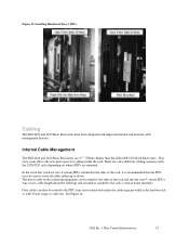
... hardware kit, or with Velcro straps or cable ties. Dell Inc. | Data Center Infrastructure 14 There are a few different cabling scenarios with improved internal and external cable management features. Any excess cable length should be routed to the rack's vertical frame members. See Figure 14. Internal Cable Management The Dell 2420 and 4220 Rack Enclosures are 2.7" (70mm) deeper than the older Dell 4210 Rack Enclosures. Figure 13: Installing Hardwired Zero U PDUs Cabling The Dell 2420...
... hardware kit, or with Velcro straps or cable ties. Dell Inc. | Data Center Infrastructure 14 There are a few different cabling scenarios with improved internal and external cable management features. Any excess cable length should be routed to the rack's vertical frame members. See Figure 14. Internal Cable Management The Dell 2420 and 4220 Rack Enclosures are 2.7" (70mm) deeper than the older Dell 4210 Rack Enclosures. Figure 13: Installing Hardwired Zero U PDUs Cabling The Dell 2420...

