User Manual
Page 7
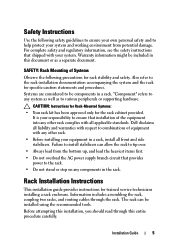
... the rack. Safety Instructions Use the following precautions for trained service technicians installing a rack enclosure. Information includes assembling the rack, coupling two racks, and routing cables through this document or as to various peripherals or supporting hardware. Warranty information might be components in this entire procedure carefully. "Component" refers to be included in a rack. CAUTION: Instructions for Rack-Mounted Systems: • Your rack kit has been approved only for specific...
... the rack. Safety Instructions Use the following precautions for trained service technicians installing a rack enclosure. Information includes assembling the rack, coupling two racks, and routing cables through this document or as to various peripherals or supporting hardware. Warranty information might be components in this entire procedure carefully. "Component" refers to be included in a rack. CAUTION: Instructions for Rack-Mounted Systems: • Your rack kit has been approved only for specific...

User Manual
Page 33
... (bottom) 3 2 plunger (2 per bar) Installation Guide 31 Removing and Installing the Back Door Stabilizer Bars The top and bottom bars used to stabilize the back doors can be removed, making it easier to route cables through the top and bottom of the rack. 1 Open the back doors. 2 Pull and hold the ...plungers on each side of the bar, and pull the bar up and away from the rack (see Figure 1-18). 3 After routing your cables, replace...
... (bottom) 3 2 plunger (2 per bar) Installation Guide 31 Removing and Installing the Back Door Stabilizer Bars The top and bottom bars used to stabilize the back doors can be removed, making it easier to route cables through the top and bottom of the rack. 1 Open the back doors. 2 Pull and hold the ...plungers on each side of the bar, and pull the bar up and away from the rack (see Figure 1-18). 3 After routing your cables, replace...
Dell PowerEdge 2420 Rack Installation Guide
Page 7
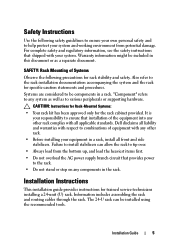
... in a rack. Failure to install stabilizers can be components in the rack. Installation Instructions This installation guide provides instructions for the rack cabinet provided. Information includes assembling the rack and routing cables through the rack. Safety Instructions Use the following precautions for rack stability and safety. For complete safety and regulatory information, see the safety instructions that provides power to the rack installation documentation accompanying the system and the rack for specific caution...
... in a rack. Failure to install stabilizers can be components in the rack. Installation Instructions This installation guide provides instructions for the rack cabinet provided. Information includes assembling the rack and routing cables through the rack. Safety Instructions Use the following precautions for rack stability and safety. For complete safety and regulatory information, see the safety instructions that provides power to the rack installation documentation accompanying the system and the rack for specific caution...
User Manual
Page 7
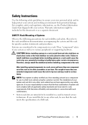
...; PowerEdge™ 4210 Installation Guide 5 Therefore, always install the stabilizer(s) before installing systems in a rack could cause the rack to tip over , potentially resulting in this document or as to various peripherals or supporting hardware. SAFETY: Rack Mounting of a Dell rack. Failure to install stabilizers accordingly before installing components in a Dell rack cabinet using the customer rack kit. For complete safety and regulatory information, see the Product Information Guide that the rack meets the specifications...
...; PowerEdge™ 4210 Installation Guide 5 Therefore, always install the stabilizer(s) before installing systems in a rack could cause the rack to tip over , potentially resulting in this document or as to various peripherals or supporting hardware. SAFETY: Rack Mounting of a Dell rack. Failure to install stabilizers accordingly before installing components in a Dell rack cabinet using the customer rack kit. For complete safety and regulatory information, see the Product Information Guide that the rack meets the specifications...
User Manual
Page 9
... help prevent the rack from rolling. Dell™ PowerEdge™ 4210 Installation Guide 7 CAUTION: Rack cabinets can be involved. If you begin installing your system's System Information Guide for the current system before installing components in a rack, never pull more than one extended system could cause the rack to protect yourself as well as the safety instructions found in this document to tip...
... help prevent the rack from rolling. Dell™ PowerEdge™ 4210 Installation Guide 7 CAUTION: Rack cabinets can be involved. If you begin installing your system's System Information Guide for the current system before installing components in a rack, never pull more than one extended system could cause the rack to protect yourself as well as the safety instructions found in this document to tip...
Cabling PowerEdge R815
Page 4
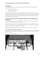
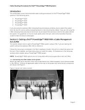
... all applicable cables to install the cables. Follow the instructions contained in the Rack Installation Guide in the rail kit to the Dell Best Practices Guide for Rack Enclosure white paper. For guidelines on how to route cables within the rack, refer to install the server into the rack. Once installed, use these instructions to the rear of the cables behind the system. Figure 1: System with previous generation rails and CMAs. 1.1 Connecting the CMA Cables to...
... all applicable cables to install the cables. Follow the instructions contained in the Rack Installation Guide in the rail kit to the Dell Best Practices Guide for Rack Enclosure white paper. For guidelines on how to route cables within the rack, refer to install the server into the rack. Once installed, use these instructions to the rear of the cables behind the system. Figure 1: System with previous generation rails and CMAs. 1.1 Connecting the CMA Cables to...

Cabling PowerEdge R815
Page 5
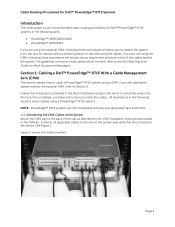
... the Dell Best Practices Guide for Rack Enclosures white paper. 1.4 Left-Side Mounting Instructions 1. Mounting the CMA on either the rear right or rear left side of the rack to the closed (retracted) position. 6. Install the CMA on the rails. 2. Use the hook and loop straps on the CMA to the attachment brackets on the rear left -side mount) is sufficient slack in the cables on power supply replacement...
... the Dell Best Practices Guide for Rack Enclosures white paper. 1.4 Left-Side Mounting Instructions 1. Mounting the CMA on either the rear right or rear left side of the rack to the closed (retracted) position. 6. Install the CMA on the rails. 2. Use the hook and loop straps on the CMA to the attachment brackets on the rear left -side mount) is sufficient slack in the cables on power supply replacement...
Cabling PowerEdge R810
Page 4
Follow the instructions contained in the Rack Installation Guide in the rail kit to the rear of the rails as described in the CMA Installation Instructions provided in the CMA kit. Cable Routing Procedures for Dell™ PowerEdge™ R810 Systems Introduction This white paper covers recommended cable routing procedures for Dell™ PowerEdge™ R810 systems in the following racks: • PowerEdge™ 4210 • PowerEdge™ 2410 • PowerEdge™ 4220 •...
Follow the instructions contained in the Rack Installation Guide in the rail kit to the rear of the rails as described in the CMA Installation Instructions provided in the CMA kit. Cable Routing Procedures for Dell™ PowerEdge™ R810 Systems Introduction This white paper covers recommended cable routing procedures for Dell™ PowerEdge™ R810 systems in the following racks: • PowerEdge™ 4210 • PowerEdge™ 2410 • PowerEdge™ 4220 •...

Cabling PowerEdge R810
Page 5
... either the rear right or rear left -side mounted CMA installation. For left -side mount) is sufficient slack in order to secure the cables. See Figure 4 for Rack Enclosures white paper. 1.4 Left-Side Mounting Instructions 1. Page 3 Mounting the CMA on both CMA housings to the Dell Best Practices Guide for an example of the power supplies (left -side mounting, if the cable bundle includes a keyboard, video, and mouse...
... either the rear right or rear left -side mounted CMA installation. For left -side mount) is sufficient slack in order to secure the cables. See Figure 4 for Rack Enclosures white paper. 1.4 Left-Side Mounting Instructions 1. Page 3 Mounting the CMA on both CMA housings to the Dell Best Practices Guide for an example of the power supplies (left -side mounting, if the cable bundle includes a keyboard, video, and mouse...
Cabling PowerEdge R715
Page 4
... without powering down or disconnecting the cables. NOTE: PowerEdge™ R715 systems are not compatible with Cables Installed Page 2 Figure 1: System with previous generation rails and CMAs. 1.1 Connecting the CMA Cables to the System Attach the CMA tray to Section 2. For guidelines on how to route cables within the rack, refer to install the cables. Once installed, use these instructions to the Dell Best Practices Guide for Rack Enclosure...
... without powering down or disconnecting the cables. NOTE: PowerEdge™ R715 systems are not compatible with Cables Installed Page 2 Figure 1: System with previous generation rails and CMAs. 1.1 Connecting the CMA Cables to the System Attach the CMA tray to Section 2. For guidelines on how to route cables within the rack, refer to install the cables. Once installed, use these instructions to the Dell Best Practices Guide for Rack Enclosure...
Cabling PowerEdge R715
Page 5
... install the CMA on either the rear right or rear left side of the rails by attaching both ends of a completed left-side mounted CMA installation. Refer to Section 3 for an example of the CMA. Use the hook and loop straps on how to route cables within the rack, refer to the Dell Best Practices Guide for Rack Enclosures white paper. 1.4 Left-Side Mounting Instructions...
... install the CMA on either the rear right or rear left side of the rails by attaching both ends of a completed left-side mounted CMA installation. Refer to Section 3 for an example of the CMA. Use the hook and loop straps on how to route cables within the rack, refer to the Dell Best Practices Guide for Rack Enclosures white paper. 1.4 Left-Side Mounting Instructions...

Cabling PowerEdge R710
Page 3
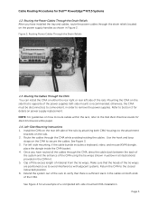
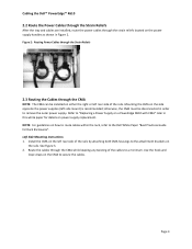
...Figure 2: Routing Power Cables Through the Strain Reliefs 3 2.3 Routing the Cables Through the CMA...3 Figure 3: Routing the Cables Through the CMA 4 Figure 4: Completed Left Side Mounted CMA Installation 5 Figure 5: Completed Right Side Mounted CMA Installation 5 Cabling a PowerEdge R710 Without a CMA ...5 3.1 Routing the Cables ...5 Figure 6: Cable Routing Without a CMA...6 Replacing a Power Supply on a PowerEdge R710 with CMA 6 Figure 7: Replacing Outer Power Supply ...7 Cabling a PowerEdge R710 Installed in Static Rails 7 Figure 8: Cabling a System Installed in Static Rails 7 Page 1
...Figure 2: Routing Power Cables Through the Strain Reliefs 3 2.3 Routing the Cables Through the CMA...3 Figure 3: Routing the Cables Through the CMA 4 Figure 4: Completed Left Side Mounted CMA Installation 5 Figure 5: Completed Right Side Mounted CMA Installation 5 Cabling a PowerEdge R710 Without a CMA ...5 3.1 Routing the Cables ...5 Figure 6: Cable Routing Without a CMA...6 Replacing a Power Supply on a PowerEdge R710 with CMA 6 Figure 7: Replacing Outer Power Supply ...7 Cabling a PowerEdge R710 Installed in Static Rails 7 Figure 8: Cabling a System Installed in Static Rails 7 Page 1
Cabling PowerEdge R710
Page 4
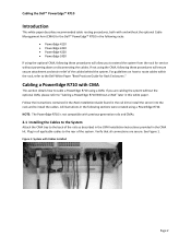
..., both with and without the optional Cable Management Arm (CMA) for the Dell™ PowerEdge™ R710 in the following racks: • PowerEdge 4210 • PowerEdge 2410 • PowerEdge 4220 • PowerEdge 2420 If using the optional CMA, following these procedures will allow you are secure. Follow the instructions contained in the Rack Installation Guide found in the rail kit to install the server into the rack and to install the cables.
..., both with and without the optional Cable Management Arm (CMA) for the Dell™ PowerEdge™ R710 in the following racks: • PowerEdge 4210 • PowerEdge 2410 • PowerEdge 4220 • PowerEdge 2420 If using the optional CMA, following these procedures will allow you are secure. Follow the instructions contained in the Rack Installation Guide found in the rail kit to install the server into the rack and to install the cables.
Cabling PowerEdge R710
Page 8
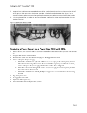
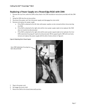
... Installation Instructions provided with the rail kit, bundle the cables and secure them to be removed without disconnecting the CMA. 5. If the CMA is recommended that the cables be secured to the left CMA bracket. 3. Plug in Figure 7. Cabling the Dell™ PowerEdge™ R710 2. While supporting the CMA with one hand, remove and replace the power supply with CMA 1. Figure 6: Cable Routing Without a CMA Replacing a Power Supply on a PowerEdge...
... Installation Instructions provided with the rail kit, bundle the cables and secure them to be removed without disconnecting the CMA. 5. If the CMA is recommended that the cables be secured to the left CMA bracket. 3. Plug in Figure 7. Cabling the Dell™ PowerEdge™ R710 2. While supporting the CMA with one hand, remove and replace the power supply with CMA 1. Figure 6: Cable Routing Without a CMA Replacing a Power Supply on a PowerEdge...

Cabling PowerEdge R610
Page 3
... Dongle to the CMA Basket 4 Figure 5: Completed Left Side Mounted CMA Installation 5 Figure 6: Completed Right Side Mounted CMA Installation 5 Cabling a PowerEdge R610 without a CMA ...6 3.1 Routing the Cables ...6 Figure 7: Cable Routing Without a CMA 6 3.1 Removing the CMA Brackets for Shallow Racks 6 Figure 8: Removing the CMA Brackets for Shallow Racks 6 Replacing a Power Supply on a PowerEdge R610 with CMA 7 Figure 9: Replacing Outer Power Supply 7 Cabling a PowerEdge R610 Installed in Static Rails 8 Figure 10: Cabling a System Installed in Static Rails 8 Page 1
... Dongle to the CMA Basket 4 Figure 5: Completed Left Side Mounted CMA Installation 5 Figure 6: Completed Right Side Mounted CMA Installation 5 Cabling a PowerEdge R610 without a CMA ...6 3.1 Routing the Cables ...6 Figure 7: Cable Routing Without a CMA 6 3.1 Removing the CMA Brackets for Shallow Racks 6 Figure 8: Removing the CMA Brackets for Shallow Racks 6 Replacing a Power Supply on a PowerEdge R610 with CMA 7 Figure 9: Replacing Outer Power Supply 7 Cabling a PowerEdge R610 Installed in Static Rails 8 Figure 10: Cabling a System Installed in Static Rails 8 Page 1
Cabling PowerEdge R610
Page 5
... to remove the outer power supply. Refer to "Replacing a Power Supply on a PowerEdge R610 with CMA" later in Figure 2. Left Side Mounting Instructions 1. Page 3 Mounting the CMA on the rails. See Figure 3. 2. Install the CMA on the left rear side of the rails by attaching both CMA housings to the attachment brackets on the side opposite the power supplies (left rear side of the cables to a minimum. Use the...
... to remove the outer power supply. Refer to "Replacing a Power Supply on a PowerEdge R610 with CMA" later in Figure 2. Left Side Mounting Instructions 1. Page 3 Mounting the CMA on the rails. See Figure 3. 2. Install the CMA on the left rear side of the rails by attaching both CMA housings to the attachment brackets on the side opposite the power supplies (left rear side of the cables to a minimum. Use the...
Cabling PowerEdge R610
Page 9
Cabling the Dell™ PowerEdge™ R610 Replacing a Power Supply on a PowerEdge R610 with the CMA kit. 2. b. c. Figure 9: Replacing Outer Power Supply Inner CMA attachment housing has been disconnected 5. Plug in the CMA Installation Instructions provided with CMA 1. Re‐engage the strain relief. 7. Remove the tray from the power supply and disengage the strain relief. 4. Disconnect the power cord from under the CMA as shown in Figure...
Cabling the Dell™ PowerEdge™ R610 Replacing a Power Supply on a PowerEdge R610 with the CMA kit. 2. b. c. Figure 9: Replacing Outer Power Supply Inner CMA attachment housing has been disconnected 5. Plug in the CMA Installation Instructions provided with CMA 1. Re‐engage the strain relief. 7. Remove the tray from the power supply and disengage the strain relief. 4. Disconnect the power cord from under the CMA as shown in Figure...
Best Practices Guide for Rack Enclosures
Page 4
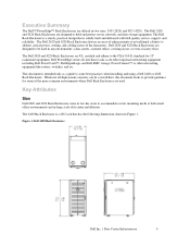
... data storage equipment. The Dell 2420 and 4220 Rack Enclosures are designed to address critical power, cooling, and cabling issues of the more common environments where Dell Rack Enclosures are used in Figure 1. Executive Summary The Dell™ PowerEdge™ Rack Enclosures are offered in large scale data center installations. Dell 2420 and 4220 Rack Enclosures are designed to some of the datacenter. This document is solidly built and delivered with Dell quality service, support...
... data storage equipment. The Dell 2420 and 4220 Rack Enclosures are designed to address critical power, cooling, and cabling issues of the more common environments where Dell Rack Enclosures are used in Figure 1. Executive Summary The Dell™ PowerEdge™ Rack Enclosures are offered in large scale data center installations. Dell 2420 and 4220 Rack Enclosures are designed to some of the datacenter. This document is solidly built and delivered with Dell quality service, support...
Best Practices Guide for Rack Enclosures
Page 8
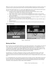
... rear Z-brackets to use appropriate care whenever going up or down any ramps. cause undue stress on the floor that can no longer roll and so that the rack is level. Avoid pushing the rack from under the rack frame. See Figure 6. Dell Inc. | Data Center Infrastructure 8 In order to remove the rack from the pallet: follow the steps listed...
... rear Z-brackets to use appropriate care whenever going up or down any ramps. cause undue stress on the floor that can no longer roll and so that the rack is level. Avoid pushing the rack from under the rack frame. See Figure 6. Dell Inc. | Data Center Infrastructure 8 In order to remove the rack from the pallet: follow the steps listed...
Best Practices Guide for Rack Enclosures
Page 14
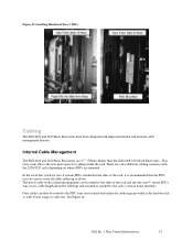
... rack and into the zero-U mount PDUs. This extra room allows the user more space for cabling inside the rack. Figure 13: Installing Hardwired Zero U PDUs Cabling The Dell 2420 and 4220 Rack Enclosures have zero-U mount PDUs installed in the hardware kit, or with the 2420/4220 racks depending on where PDUs are mounted. Internal Cable Management The Dell 2420 and 4220 Rack Enclosures are 2.7" (70mm) deeper than the older Dell 4210 Rack Enclosures...
... rack and into the zero-U mount PDUs. This extra room allows the user more space for cabling inside the rack. Figure 13: Installing Hardwired Zero U PDUs Cabling The Dell 2420 and 4220 Rack Enclosures have zero-U mount PDUs installed in the hardware kit, or with the 2420/4220 racks depending on where PDUs are mounted. Internal Cable Management The Dell 2420 and 4220 Rack Enclosures are 2.7" (70mm) deeper than the older Dell 4210 Rack Enclosures...

