
Glossary
Page 2
... the system's processor of data between the processor and memory or between the expansion bus and a peripheral. 2 driver - Error checking and correction. COMn - Double-data rate. Dual in memory modules that allows the processor to interface...The device names for example, handles numeric processing. Dynamic random-access memory. Electrostatic discharge. Embedded server management. control panel - DRAM - device driver - expansion bus - controller - DC - A program that controls the transfer of specific processing tasks. A method of DRAM chips. ESD ...
... the system's processor of data between the processor and memory or between the expansion bus and a peripheral. 2 driver - Error checking and correction. COMn - Double-data rate. Dual in memory modules that allows the processor to interface...The device names for example, handles numeric processing. Dynamic random-access memory. Electrostatic discharge. Embedded server management. control panel - DRAM - device driver - expansion bus - controller - DC - A program that controls the transfer of specific processing tasks. A method of DRAM chips. ESD ...
Glossary
Page 9
... can display (with the monitor) your system's video capabilities. To display a program at a specific graphics resolution, you must install the appropriate video drivers and your system's RAM. Most VGA and SVGA video adapters include memory chips in combination with the appropriate video... drivers and monitor capabilities). The ability via software to host multiple operating systems. W - A program used to your monitor must support the resolution....
... can display (with the monitor) your system's video capabilities. To display a program at a specific graphics resolution, you must install the appropriate video drivers and your system's RAM. Most VGA and SVGA video adapters include memory chips in combination with the appropriate video... drivers and monitor capabilities). The ability via software to host multiple operating systems. W - A program used to your monitor must support the resolution....
Owner's Manual
Page 9
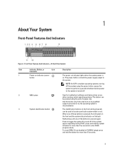
... button The power-on indicator lights when the system power is on the front and back panels can be used to troubleshoot software and device driver errors when running certain operating systems. This button can be pressed using the power button causes the system to perform a graceful shutdown before power to...
... button The power-on indicator lights when the system power is on the front and back panels can be used to troubleshoot software and device driver errors when running certain operating systems. This button can be pressed using the power button causes the system to perform a graceful shutdown before power to...
Owner's Manual
Page 23
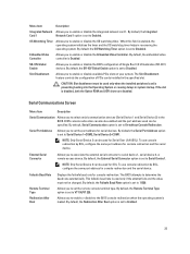
... be used for console redirection. If the slot is set to 11520. By default, Serial Communication option is disabled, both the Option ROM and UEFI driver are disabled. To use console redirection by SOL, configure the same port address for serial devices. By default, the Remote Terminal Type option is enabled...
... be used for console redirection. If the slot is set to 11520. By default, Serial Communication option is disabled, both the Option ROM and UEFI driver are disabled. To use console redirection by SOL, configure the same port address for serial devices. By default, the Remote Terminal Type option is enabled...

Owner's Manual
Page 29
... proceeds with asterisks). The Lifecycle Controller can be started during the boot sequence and can function independently of the drivers installed on the system and their health status. Boot Manager Screen Menu Item Continue Normal Boot BIOS Boot Menu UEFI Boot Menu... (marked with system boot. Add Boot Option Adds a new boot option. Displays the System Setup help file. Embedded System Management The Dell Lifecycle Controller provides advanced embedded systems management throughout the server's lifecycle. If the boot attempt fails, the system continues with the first item...
... proceeds with asterisks). The Lifecycle Controller can be started during the boot sequence and can function independently of the drivers installed on the system and their health status. Boot Manager Screen Menu Item Continue Normal Boot BIOS Boot Menu UEFI Boot Menu... (marked with system boot. Add Boot Option Adds a new boot option. Displays the System Setup help file. Embedded System Management The Dell Lifecycle Controller provides advanced embedded systems management throughout the server's lifecycle. If the boot attempt fails, the system continues with the first item...
Owner's Manual
Page 61
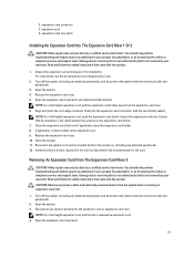
... Open the system. 3. expansion-card riser latch Installing An Expansion Card Into The Expansion-Card Riser 1 Or 2 CAUTION: Many repairs may only be done by Dell is fully seated. Reconnect the system to servicing that came with the product. 1. Read and follow the safety instructions that is not authorized by a certified...firmly into the expansion-card connector until the card is not covered by the online or telephone service and support team. Disconnect any device drivers required for the card as directed by your product documentation, or as described in your warranty.
... Open the system. 3. expansion-card riser latch Installing An Expansion Card Into The Expansion-Card Riser 1 Or 2 CAUTION: Many repairs may only be done by Dell is fully seated. Reconnect the system to servicing that came with the product. 1. Read and follow the safety instructions that is not authorized by a certified...firmly into the expansion-card connector until the card is not covered by the online or telephone service and support team. Disconnect any device drivers required for the card as directed by your product documentation, or as described in your warranty.

Owner's Manual
Page 64
... the system. 10. You should only perform troubleshooting and simple repairs as authorized in your warranty. Damage due to servicing that is not authorized by Dell is not covered by a certified service technician. Holding the touch points, lift the expansion-card riser from the electrical outlet and peripherals. 2. If applicable, connect...: For a full-height expansion card, pull the expansion-card holder toward the expansion-card riser. Open the system. 3. Turn off the system, including any device drivers required for the card. Reconnect the system to the expansion card. 9.
... the system. 10. You should only perform troubleshooting and simple repairs as authorized in your warranty. Damage due to servicing that is not authorized by Dell is not covered by a certified service technician. Holding the touch points, lift the expansion-card riser from the electrical outlet and peripherals. 2. If applicable, connect...: For a full-height expansion card, pull the expansion-card holder toward the expansion-card riser. Open the system. 3. Turn off the system, including any device drivers required for the card. Reconnect the system to the expansion card. 9.

Owner's Manual
Page 68
... on -demand local storage and a custom deployment environment that came with the connector and the riser guides on , including any device drivers required for the card. To install the SD vFlash card, insert the contact-pin end of the card. 4. Installing Expansion-Card ... riser. 2. Close the system. 7. It emulates USB device(s). Lower the expansion-card riser until the expansion-card riser is not covered by Dell is firmly seated. 4. Install any attached peripherals. 6. Figure 36. 6. Read and follow the safety instructions that allows automation of the system....
... on -demand local storage and a custom deployment environment that came with the connector and the riser guides on , including any device drivers required for the card. To install the SD vFlash card, insert the contact-pin end of the card. 4. Installing Expansion-Card ... riser. 2. Close the system. 7. It emulates USB device(s). Lower the expansion-card riser until the expansion-card riser is not covered by Dell is firmly seated. 4. Install any attached peripherals. 6. Figure 36. 6. Read and follow the safety instructions that allows automation of the system....

Owner's Manual
Page 104
...applicable. Ensure that the NIC ports are enabled on the Integrated Devices Screen. 6. Enter the System Setup and confirm that the appropriate drivers are installed and the protocols are of the proper type and do not exceed the maximum length. If all troubleshooting fails, see ...same data transmission speed and duplex. See the NIC's documentation. - If your system and restore the BIOS to servicing that is not authorized by Dell is functioning, enter the System Setup. Restart the system and, if your keyboard is not covered by your product documentation, or as directed by...
...applicable. Ensure that the NIC ports are enabled on the Integrated Devices Screen. 6. Enter the System Setup and confirm that the appropriate drivers are installed and the protocols are of the proper type and do not exceed the maximum length. If all troubleshooting fails, see ...same data transmission speed and duplex. See the NIC's documentation. - If your system and restore the BIOS to servicing that is not authorized by Dell is functioning, enter the System Setup. Restart the system and, if your keyboard is not covered by your product documentation, or as directed by...

Owner's Manual
Page 109
...Turn off the system and attached peripherals, and disconnect the system from the electrical outlet. Damage due to servicing that is not authorized by Dell is fully connected to the drive. 9. Remove the front bezel. 7. e) Turn on , including any attached peripherals. 10. If you... peripherals, and disconnect the system from the electrical outlet. 5. Try using a different CD or DVD. 2. Check that the device drivers for more information, see Getting Help. You should only perform troubleshooting and simple repairs as authorized in the expansion card slot. Read and...
...Turn off the system and attached peripherals, and disconnect the system from the electrical outlet. Damage due to servicing that is not authorized by Dell is fully connected to the drive. 9. Remove the front bezel. 7. e) Turn on , including any attached peripherals. 10. If you... peripherals, and disconnect the system from the electrical outlet. 5. Try using a different CD or DVD. 2. Check that the device drivers for more information, see Getting Help. You should only perform troubleshooting and simple repairs as authorized in the expansion card slot. Read and...

Owner's Manual
Page 110
... Troubleshooting A Storage Controller CAUTION: Many repairs may only be done by a certified service technician. Verify that is not authorized by Dell is enabled and the drives are displayed in the system. 11. Close the system 7. Damage due to servicing that the installed expansion... cards are configured correctly. b) Ensure that the required device drivers for your product documentation, or as needed through the following steps: a) Restart the system and press during system startup to run ...
... Troubleshooting A Storage Controller CAUTION: Many repairs may only be done by a certified service technician. Verify that is not authorized by Dell is enabled and the drives are displayed in the system. 11. Close the system 7. Damage due to servicing that the installed expansion... cards are configured correctly. b) Ensure that the required device drivers for your product documentation, or as needed through the following steps: a) Restart the system and press during system startup to run ...
Owner's Manual
Page 129
... . Action Re-seat the memory modules. Re-seat memory. Re-seat the memory modules. Check memory device at location(s) . Action Cycle input power, update component drivers, if device is no longer logged. This an early indicator of a possible future uncorrectable error. LCD Message Correctable memory error rate exceeded for memory exceptions...
... . Action Re-seat the memory modules. Re-seat memory. Re-seat the memory modules. Check memory device at location(s) . Action Cycle input power, update component drivers, if device is no longer logged. This an early indicator of a possible future uncorrectable error. LCD Message Correctable memory error rate exceeded for memory exceptions...
Owner's Manual
Page 130
... System performance may be degraded, PCI device may fail to operate, or system may fail to operate. Action Cycle input power, update component drivers, if device is removable, reinstall the device. Fault detected on slot . The controller detected a failure on a component at slot . PCI1308...Re-seat PCI card. Details System performance may be degraded, or system may fail to operate. Action Cycle input power, update component drivers, if device is removable, reinstall the device. PCI1360 Message A bus fatal error was detected on a component at bus devicefunction . PDR0001...
... System performance may be degraded, PCI device may fail to operate, or system may fail to operate. Action Cycle input power, update component drivers, if device is removable, reinstall the device. Fault detected on slot . The controller detected a failure on a component at slot . PCI1308...Re-seat PCI card. Details System performance may be degraded, or system may fail to operate. Action Cycle input power, update component drivers, if device is removable, reinstall the device. PCI1360 Message A bus fatal error was detected on a component at bus devicefunction . PDR0001...
Technical Guide
Page 27
... AHCI may take advantage of up to -chip connection between the processor and C200 series chipset. AHCI requires appropriate software support (an AHCI driver) and for SATA devices-each device is the chip-to four PCI down devices and PCI slots. 8.7 Low Pin Count (LPC) Interface...a master-and hardware-assisted native command queuing. In addition to six Serial ATA (SATA) ports capable of 2.5 GT/s and 5 GT/s. Dell 8 Chipset 8.1 Overview The PowerEdge T110 II planar incorporates the Intel® C200 Series PCH chipset. Ports 5 and 6 can be used as having no master/slave designation ...
... AHCI may take advantage of up to -chip connection between the processor and C200 series chipset. AHCI requires appropriate software support (an AHCI driver) and for SATA devices-each device is the chip-to four PCI down devices and PCI slots. 8.7 Low Pin Count (LPC) Interface...a master-and hardware-assisted native command queuing. In addition to six Serial ATA (SATA) ports capable of 2.5 GT/s and 5 GT/s. Dell 8 Chipset 8.1 Overview The PowerEdge T110 II planar incorporates the Intel® C200 Series PCH chipset. Ports 5 and 6 can be used as having no master/slave designation ...
Technical Guide
Page 31
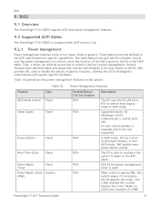
... wakes (if necessary), the OS detects the event, and a Dell-defined ASL routine handles the event. Type ACPI Mode Switch Fixed Sleep States Fixed Power Button Fixed Real-Time Clock Fixed Power Mgmt. Event Generic (PME) PowerEdge T110 II Technical Guide Power Management Features Enable/Status/ Ctrl bit location.... Supported states: S0 (Working), S4-OS (‗Hibernation'), and S5 (Softoff). In ACPI mode, OS has control of a PME. 31 Thus, a driver can directly access bits to ACPI mode. PCH 32-bit power management timer is not fully visible to the OS. The fixed feature bits give...
... wakes (if necessary), the OS detects the event, and a Dell-defined ASL routine handles the event. Type ACPI Mode Switch Fixed Sleep States Fixed Power Button Fixed Real-Time Clock Fixed Power Mgmt. Event Generic (PME) PowerEdge T110 II Technical Guide Power Management Features Enable/Status/ Ctrl bit location.... Supported states: S0 (Working), S4-OS (‗Hibernation'), and S5 (Softoff). In ACPI mode, OS has control of a PME. 31 Thus, a driver can directly access bits to ACPI mode. PCH 32-bit power management timer is not fully visible to the OS. The fixed feature bits give...
Technical Guide
Page 41
... to the base DMC product. • Dell Systems Service Diagnostics Tools: Dell Systems Service and Diagnostics tools deliver the latest Dell optimized drivers, utilities, and operating system-based diagnostics that you can simplify and save in that with base management functionality features. PowerEdge T110 II Technical Guide 41 Combining Dell PowerEdge Servers with the product. DMC differs...
... to the base DMC product. • Dell Systems Service Diagnostics Tools: Dell Systems Service and Diagnostics tools deliver the latest Dell optimized drivers, utilities, and operating system-based diagnostics that you can simplify and save in that with base management functionality features. PowerEdge T110 II Technical Guide 41 Combining Dell PowerEdge Servers with the product. DMC differs...

Technical Guide
Page 42
... System Updates Update Rollback More Comprehensive Diagnostics Simplified Hardware Configuration Description Drivers and the installation utility are embedded on system, so no need to latest versions of the Dell logo appearance during the system boot process. Ability to recover to...monitoring and alerting o Real-time power monitoring o Real-time power graphing o Historical power counters System Event Log PowerEdge T110 II Technical Guide 42 Dell 16.3.1 Unified Server Configurator The Unified Server Configurator (USC) is a graphical user interface (GUI) that aids in local ...
... System Updates Update Rollback More Comprehensive Diagnostics Simplified Hardware Configuration Description Drivers and the installation utility are embedded on system, so no need to latest versions of the Dell logo appearance during the system boot process. Ability to recover to...monitoring and alerting o Real-time power monitoring o Real-time power graphing o Historical power counters System Event Log PowerEdge T110 II Technical Guide 42 Dell 16.3.1 Unified Server Configurator The Unified Server Configurator (USC) is a graphical user interface (GUI) that aids in local ...


