EMC Systems Management Overview Guide Version 20.0
Page 12
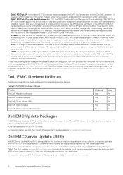
... offers a library of technical white papers detailing the use of a standard, machine-readable schema, with Redfish support. For more information, see www.dell.com/support/article/sln311300 and www.dell.com/support/article/ sln311809. Dell EMC Update Utilities The ...PowerEdge platforms. With DRM you run SUU on a server and applications like OMSA and iSM. For more information, see Dell EMC Update Utility User's Guide available at www.dell.com/esmmanuals. 12 Systems Management Product Overview Dell EMC Update Utilities Product Dell EMC Repository Manager Dell EMC Update Packages Dell...
... offers a library of technical white papers detailing the use of a standard, machine-readable schema, with Redfish support. For more information, see www.dell.com/support/article/sln311300 and www.dell.com/support/article/ sln311809. Dell EMC Update Utilities The ...PowerEdge platforms. With DRM you run SUU on a server and applications like OMSA and iSM. For more information, see Dell EMC Update Utility User's Guide available at www.dell.com/esmmanuals. 12 Systems Management Product Overview Dell EMC Update Utilities Product Dell EMC Repository Manager Dell EMC Update Packages Dell...
Lifecycle Controller Version Remote Services Quick Start Guide
Page 14
... or documentation or advanced technical reference material intended for users or technicians. • The Dell iDRAC Licensing White paper at www.dell.com/support or www.dell.com/idracmanuals: • The Lifecycle Controller Online Help provides information about the fields available on target systems. • The PowerEdge RAID Controller (PERC) 9 User's Guide provides specification and configuration...
... or documentation or advanced technical reference material intended for users or technicians. • The Dell iDRAC Licensing White paper at www.dell.com/support or www.dell.com/idracmanuals: • The Lifecycle Controller Online Help provides information about the fields available on target systems. • The PowerEdge RAID Controller (PERC) 9 User's Guide provides specification and configuration...

EMC Installation and Service Manual
Page 11
... error information that are up to install drives that can be used in troubleshooting the system. For more information, see the iDRAC User's Guide available at https://www.dell.com/idracmanuals 2 Optical drive blank N/A 3 Drive N/A 4 Right control panel N/A 5 Information tag For the 8 x 3.5-inch drive system, a optical drive bay blank is a slide-out... the secure default access to identify any failed hardware components. NOTE: The iDRAC Quick Sync 2 indicator is optional. For more information about drives, see the Technical Specifications section.
... error information that are up to install drives that can be used in troubleshooting the system. For more information, see the iDRAC User's Guide available at https://www.dell.com/idracmanuals 2 Optical drive blank N/A 3 Drive N/A 4 Right control panel N/A 5 Information tag For the 8 x 3.5-inch drive system, a optical drive bay blank is a slide-out... the secure default access to identify any failed hardware components. NOTE: The iDRAC Quick Sync 2 indicator is optional. For more information about drives, see the Technical Specifications section.
EMC Installation and Service Manual
Page 13
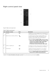
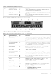
...AB features. Right control panel view Table 4. NOTE: You can configure iDRAC Direct by cable quality. NOTE: For more information, see the Technical Specifications section. Right control panel Item Indicator or button Icon 1 VGA port 2 iDRAC Direct port (Micro-AB USB) 3 USB 2.0-compliant ... information on or off the system. System overview 13 The USB port is powered on the ports, see the iDRAC User's Guide available at https://www.dell.com/idracmanuals . Indicates if the system is a 4-pin connector and 2.0-compliant. Cable length should not exceed 3 feet (0.91...
...AB features. Right control panel view Table 4. NOTE: You can configure iDRAC Direct by cable quality. NOTE: For more information, see the Technical Specifications section. Right control panel Item Indicator or button Icon 1 VGA port 2 iDRAC Direct port (Micro-AB USB) 3 USB 2.0-compliant ... information on or off the system. System overview 13 The USB port is powered on the ports, see the iDRAC User's Guide available at https://www.dell.com/idracmanuals . Indicates if the system is a 4-pin connector and 2.0-compliant. Cable length should not exceed 3 feet (0.91...

EMC Installation and Service Manual
Page 14
.... Enables you to connect PCI Express expansion cards. This port is USB 2.0-compliant. For more information about the PSU configurations, see Technical Specifications section. The expansion card riser enables you to connect a display device to connect PCI Express expansion cards. For more information on.... • If the system stops responding during POST, press and hold the button for more information, see the iDRAC User's Guide at www.dell.com/poweredgemanuals. Enables you to connect PCI Express expansion cards. For more than 16 seconds. To reset iDRAC, press and hold...
.... Enables you to connect PCI Express expansion cards. This port is USB 2.0-compliant. For more information about the PSU configurations, see Technical Specifications section. The expansion card riser enables you to connect a display device to connect PCI Express expansion cards. For more information on.... • If the system stops responding during POST, press and hold the button for more information, see the iDRAC User's Guide at www.dell.com/poweredgemanuals. Enables you to connect PCI Express expansion cards. For more than 16 seconds. To reset iDRAC, press and hold...

EMC Installation and Service Manual
Page 15
... drive module N/A Enables you to the system. For more information, see the Technical Specifications section. The expansion card riser enables you to the system board. For more information about the PSU configurations, see the iDRAC User's Guide at www.dell.com/poweredgemanuals. For more information on the expansion cards that are supported on...
... drive module N/A Enables you to the system. For more information, see the Technical Specifications section. The expansion card riser enables you to the system board. For more information about the PSU configurations, see the iDRAC User's Guide at www.dell.com/poweredgemanuals. For more information on the expansion cards that are supported on...
EMC Installation and Service Manual
Page 184
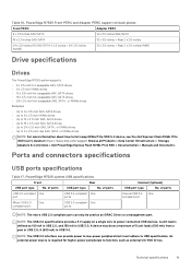
... USB port type No. Table 68. PowerEdge R7525 Front PERC and Adapter PERC support on a single wire to hot swap NVMe PCIe SSD U.2 device, see the Dell Express Flash NVMe PCIe SSD User's Guide at https://www.dell.com/support Browse all Products > Data Center Infrastructure > Storage Adapters & Controllers > Dell PowerEdge Express Flash NVMe PCIe SSD > Documentation...
... USB port type No. Table 68. PowerEdge R7525 Front PERC and Adapter PERC support on a single wire to hot swap NVMe PCIe SSD U.2 device, see the Dell Express Flash NVMe PCIe SSD User's Guide at https://www.dell.com/support Browse all Products > Data Center Infrastructure > Storage Adapters & Controllers > Dell PowerEdge Express Flash NVMe PCIe SSD > Documentation...
EMC Technical Specifications
Page 7
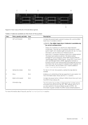
...System overview 7 There are up to install drives that are supported on . For more information about drives, see the Technical Specifications section. For more information about the ports, see the Drives section. The Information tag is optional. Front view... LED indicators section. • Quick Sync 2 (wireless): Indicates a Quick Sync enabled system. For more information, see the iDRAC User's Guide available at https://www.dell.com/idracmanuals 2 Optical drive blank N/A 3 Drive N/A 4 Right control panel N/A 5 Information tag For the 8 x 3.5-inch drive system...
...System overview 7 There are up to install drives that are supported on . For more information about drives, see the Technical Specifications section. For more information about the ports, see the Drives section. The Information tag is optional. Front view... LED indicators section. • Quick Sync 2 (wireless): Indicates a Quick Sync enabled system. For more information, see the iDRAC User's Guide available at https://www.dell.com/idracmanuals 2 Optical drive blank N/A 3 Drive N/A 4 Right control panel N/A 5 Information tag For the 8 x 3.5-inch drive system...
EMC Technical Specifications
Page 9
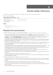
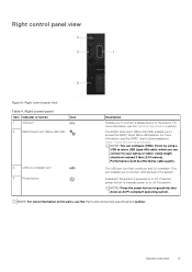
...Cable length should not exceed 3 feet (0.91 meters). System overview 9 NOTE: For more information, see the iDRAC User's Guide available at https://www.dell.com/idracmanuals . NOTE: Press the power button to access the iDRAC Direct Micro-AB features. Right control panel view Figure ... USB devices to manually power on or off the system. Press the power button to the system. For more information, see the Technical Specifications section. Right control panel view Table 4. Right control panel Item Indicator or button Icon 1 VGA port 2 iDRAC Direct port ...
...Cable length should not exceed 3 feet (0.91 meters). System overview 9 NOTE: For more information, see the iDRAC User's Guide available at https://www.dell.com/idracmanuals . NOTE: Press the power button to access the iDRAC Direct Micro-AB features. Right control panel view Figure ... USB devices to manually power on or off the system. Press the power button to the system. For more information, see the Technical Specifications section. Right control panel view Table 4. Right control panel Item Indicator or button Icon 1 VGA port 2 iDRAC Direct port ...
EMC Technical Specifications
Page 10
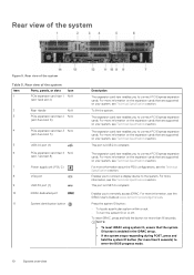
... (for more information, see the iDRAC User's Guide at www.dell.com/poweredgemanuals. For more than 5 seconds) to connect PCI Express expansion cards. Press the system ID button: • To locate a particular system within a rack. • To turn the system ID on your system, see Technical Specifications section. Rear view of the system...
... (for more information, see the iDRAC User's Guide at www.dell.com/poweredgemanuals. For more than 5 seconds) to connect PCI Express expansion cards. Press the system ID button: • To locate a particular system within a rack. • To turn the system ID on your system, see Technical Specifications section. Rear view of the system...
EMC Technical Specifications
Page 11
...on your system, see the Technical Specifications section. For more information on the expansion cards that are supported on your system, see the iDRAC User's Guide at www.dell.com/poweredgemanuals. For more information about the ports, see the Technical Specifications section. The NIC ...ports are embedded on the LOM card that are integrated on your system, see the Technical Specifications section. The expansion card...
...on your system, see the Technical Specifications section. For more information on the expansion cards that are supported on your system, see the iDRAC User's Guide at www.dell.com/poweredgemanuals. For more information about the ports, see the Technical Specifications section. The NIC ...ports are embedded on the LOM card that are integrated on your system, see the Technical Specifications section. The expansion card...
EMC Technical Specifications
Page 19
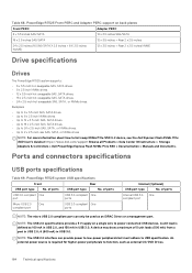
...can only be used as an iDRAC Direct or a management port. A device may draw a maximum of ports Internal USB 3.0- PowerEdge R7525 system USB specifications Front Rear USB port type No. Technical specifications 19 of 5 unit loads (500 mA) from a port in USB 2.0; 6 (900 mA) in USB 3.0. A ...USB 2.0, and 150 mA in USB 3.0. Table 16. PowerEdge R7525 Front PERC and Adapter PERC support on a single wire to hot swap NVMe PCIe SSD U.2 device, see the Dell Express Flash NVMe PCIe SSD User's Guide at https://www.dell.com/support Browse all Products > Data Center Infrastructure > ...
...can only be used as an iDRAC Direct or a management port. A device may draw a maximum of ports Internal USB 3.0- PowerEdge R7525 system USB specifications Front Rear USB port type No. Technical specifications 19 of 5 unit loads (500 mA) from a port in USB 2.0; 6 (900 mA) in USB 3.0. A ...USB 2.0, and 150 mA in USB 3.0. Table 16. PowerEdge R7525 Front PERC and Adapter PERC support on a single wire to hot swap NVMe PCIe SSD U.2 device, see the Dell Express Flash NVMe PCIe SSD User's Guide at https://www.dell.com/support Browse all Products > Data Center Infrastructure > ...
EMC PowerEdge Servers with NVIDIA GPUs and VMware vSphere
Page 8
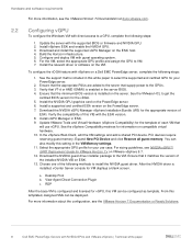
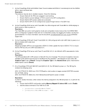
... server BIOS. 4. Install the NVIDIA GPU graphics card on the PowerEdge server. 7. RDP After the base VM is installed, vCenter Server...Guide for information on ESXi. 13. Choose one of each VM that will use case. See the vSphere Compatibility matrixes for VMware Horizon 7.x on a Dell EMC PowerEdge... GPU. 2. Install a supported and certified ESXi version on the PowerEdge server. 6. Expand New PCI Device and click Reserve all guest ...12. After the NVIDIA driver is configured and licensed for your PowerEdge server. 2. Download the NVIDIA guest driver installer package to ...
... server BIOS. 4. Install the NVIDIA GPU graphics card on the PowerEdge server. 7. RDP After the base VM is installed, vCenter Server...Guide for information on ESXi. 13. Choose one of each VM that will use case. See the vSphere Compatibility matrixes for VMware Horizon 7.x on a Dell EMC PowerEdge... GPU. 2. Install a supported and certified ESXi version on the PowerEdge server. 6. Expand New PCI Device and click Reserve all guest ...12. After the NVIDIA driver is configured and licensed for your PowerEdge server. 2. Download the NVIDIA guest driver installer package to ...
EMC PowerEdge Servers with NVIDIA GPUs and VMware vSphere
Page 17
...mode and not in computation mode. For more information, see the document GPUMODESWITCH User Guide at NVIDIA support site. 9. Note that the BIOS configuration setting Memory Mapped I/O above...tool gpumodeswitch. On the PowerEdge R740 with Tesla T4 and ESXi 6.5, VM configured with vGPU power-on . - On a PowerEdge R730 with NVIDIA GPUs and VMware vSphere | Technical white paper Known issues ... the correct wattage of VM: o pciPassthru.use64bitMMIO="TRUE" o pciPassthru.64bitMMIOSizeGB = "64" 17 Dell EMC PowerEdge Servers with M60 GPU and ESXi 6.5 U3, the VM failed to power-on or fails to...
...mode and not in computation mode. For more information, see the document GPUMODESWITCH User Guide at NVIDIA support site. 9. Note that the BIOS configuration setting Memory Mapped I/O above...tool gpumodeswitch. On the PowerEdge R740 with Tesla T4 and ESXi 6.5, VM configured with vGPU power-on . - On a PowerEdge R730 with NVIDIA GPUs and VMware vSphere | Technical white paper Known issues ... the correct wattage of VM: o pciPassthru.use64bitMMIO="TRUE" o pciPassthru.64bitMMIOSizeGB = "64" 17 Dell EMC PowerEdge Servers with M60 GPU and ESXi 6.5 U3, the VM failed to power-on or fails to...


