
Getting Started Guide
Page 6
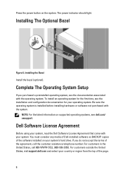
... software installed on your country or region from the top of the agreement, call 800-WWW-DELL (800-999-3355). For customers outside the United States, visit support.dell.com and select your system's hard drive. Installing the Bezel Install the bezel (optional). NOTE...purchased with your operating system. If you purchased a preinstalled operating system, see dell.com/ ossupport. Installing The Optional Bezel Figure 6. For customers in the United States, call the customer assistance telephone number. To install an operating system for the first time, see the installation ...
... software installed on your country or region from the top of the agreement, call 800-WWW-DELL (800-999-3355). For customers outside the United States, visit support.dell.com and select your system's hard drive. Installing the Bezel Install the bezel (optional). NOTE...purchased with your operating system. If you purchased a preinstalled operating system, see dell.com/ ossupport. Installing The Optional Bezel Figure 6. For customers in the United States, call the customer assistance telephone number. To install an operating system for the first time, see the installation ...

Getting Started Guide
Page 7
...this document in compliance with the requirements of the official Mexican standards (NOM): Importer: Dell Inc. Obtaining Technical Assistance If you purchased with your Owner's Manual. See dell.com/training for updates on the device described in this guide or if the system.... NOM Information The following information is available online at support.dell.com/manuals. • The rack documentation included with your rack solution describes how to troubleshoot the system and install or replace system components. Model number: Supply voltage: E14S 100-240 V CA (with 495 ...
...this document in compliance with the requirements of the official Mexican standards (NOM): Importer: Dell Inc. Obtaining Technical Assistance If you purchased with your Owner's Manual. See dell.com/training for updates on the device described in this guide or if the system.... NOM Information The following information is available online at support.dell.com/manuals. • The rack documentation included with your rack solution describes how to troubleshoot the system and install or replace system components. Model number: Supply voltage: E14S 100-240 V CA (with 495 ...

Owner's Manual
Page 14
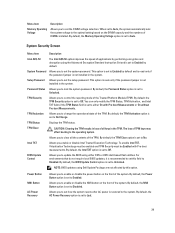
...display error status during system startup. Power Displays the power output of the Host, Model, or User String for the system Number Displays the Asset tag or the Service tag for example, a failed fan or hard drive) Corrective Action None required. Name... indicator lights solid blue. Diagnostic Indicators NOTE: The diagnostic indicators are configured in Celsius or Fahrenheit. The diagnostic indicators on PowerEdge R720xd. See Getting Help. Electrical indicator Condition The indicator blinks amber if the system experiences an electrical error (for Corrective Action...
...display error status during system startup. Power Displays the power output of the Host, Model, or User String for the system Number Displays the Asset tag or the Service tag for example, a failed fan or hard drive) Corrective Action None required. Name... indicator lights solid blue. Diagnostic Indicators NOTE: The diagnostic indicators are configured in Celsius or Fahrenheit. The diagnostic indicators on PowerEdge R720xd. See Getting Help. Electrical indicator Condition The indicator blinks amber if the system experiences an electrical error (for Corrective Action...
Owner's Manual
Page 24
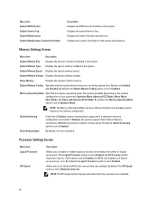
..., the System Memory Testing option is set to Disabled. By default, Node Interleaving option is set to enable or disable logical processors and display the number of logical processors. NOTE: The QPI speed option displays only when both the processors are run during system boot. System Memory Voltage Displays the system...
..., the System Memory Testing option is set to Disabled. By default, Node Interleaving option is set to enable or disable logical processors and display the number of logical processors. NOTE: The QPI speed option displays only when both the processors are run during system boot. System Memory Voltage Displays the system...
Owner's Manual
Page 25
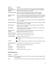
...enable or disable Data Cache Unit streamer prefetcher. DCU Streamer Prefetcher Allows you to SATA port A. Displays the total L2 cache. Number of random memory access. Processor 64-bit Support Specifies if the processor(s) support 64-bit extensions. Displays the brand name reported ...by Intel. Displays the total L3 cache. Virtualization Technology Allows you to control the number of enabled cores in each processor installed in normal mode for applications that require high utilization of Cores per Processor option is...
...enable or disable Data Cache Unit streamer prefetcher. DCU Streamer Prefetcher Allows you to SATA port A. Displays the total L2 cache. Number of random memory access. Processor 64-bit Support Specifies if the processor(s) support 64-bit extensions. Displays the brand name reported ...by Intel. Displays the total L3 cache. Virtualization Technology Allows you to control the number of enabled cores in each processor installed in normal mode for applications that require high utilization of Cores per Processor option is...
Owner's Manual
Page 29
... to Off. By default, the TPM Clear option is set to Auto. Intel TXT Allows you to lock the system password. NOTE: BIOS updates using Dell Update Package are not affected by default. By default, the AC Power Recovery option is set to Unlocked. By default, the Memory Operating Voltage option... Voltage Allows you to set to Auto, the system automatically sets the system voltage to the optimal setting based on the DIMM capacity and the numbers of DIMMs installed. Allows you to enable or disable the NMI button on the front of the system.
... to Off. By default, the TPM Clear option is set to Auto. Intel TXT Allows you to lock the system password. NOTE: BIOS updates using Dell Update Package are not affected by default. By default, the AC Power Recovery option is set to Unlocked. By default, the Memory Operating Voltage option... Voltage Allows you to set to Auto, the system automatically sets the system voltage to the optimal setting based on the DIMM capacity and the numbers of DIMMs installed. Allows you to enable or disable the NMI button on the front of the system.

Owner's Manual
Page 31
To assign a system and/or setup password: 1. In the System BIOS screen, select System Security and press . The password can contain the numbers 0 through 9. - Select Setup Password, enter your system password, and press or . In the System Setup Main Menu, select System BIOS and press . In the System ...
To assign a system and/or setup password: 1. In the System BIOS screen, select System Security and press . The password can contain the numbers 0 through 9. - Select Setup Password, enter your system password, and press or . In the System Setup Main Menu, select System BIOS and press . In the System ...
Owner's Manual
Page 32
... down and restart the system, the error message is displayed until the correct password is Locked, type the password and press when prompted at reboot. Number of the System Setup options. Press to return to the system. Must power down . You have assigned a setup password, the system accepts your system from...
... down and restart the system, the error message is displayed until the correct password is Locked, type the password and press when prompted at reboot. Number of the System Setup options. Press to return to the system. Must power down . You have assigned a setup password, the system accepts your system from...

Owner's Manual
Page 35
Rotate the left end of removing insulation from size 10 AWG solid or stranded, insulated copper wire NOTE: Use alpha wire part number 3080 or equivalent (65/30 stranding). Figure 12. Lift the release latch next to ground Following tools are required for assembling cables for a DC power ...
Rotate the left end of removing insulation from size 10 AWG solid or stranded, insulated copper wire NOTE: Use alpha wire part number 3080 or equivalent (65/30 stranding). Figure 12. Lift the release latch next to ground Following tools are required for assembling cables for a DC power ...
Owner's Manual
Page 41
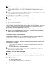
...can be 1600 MT/s, 1333 MT/s, 1066 MT/s, or 800 MT/s depending on: • DIMM type (UDIMM, RDIMM, or LRDIMM) NOTE: PowerEdge R720xd with 3.5 inch hard-drive configuration does not support LRDIMMs due to processor 2. 41 NOTE: DIMMs in sockets A1 to A12 are assigned to... In each channel, the release levers of the first socket are assigned to thermal limitations. • DIMM configuration (number of ranks) • maximum frequency of the DIMMs • number of DIMMs populated per channel • DIMM operating voltage • system profile selected (for example, Performance Optimized, ...
...can be 1600 MT/s, 1333 MT/s, 1066 MT/s, or 800 MT/s depending on: • DIMM type (UDIMM, RDIMM, or LRDIMM) NOTE: PowerEdge R720xd with 3.5 inch hard-drive configuration does not support LRDIMMs due to processor 2. 41 NOTE: DIMMs in sockets A1 to A12 are assigned to... In each channel, the release levers of the first socket are assigned to thermal limitations. • DIMM configuration (number of ranks) • maximum frequency of the DIMMs • number of DIMMs populated per channel • DIMM operating voltage • system profile selected (for example, Performance Optimized, ...
Owner's Manual
Page 45
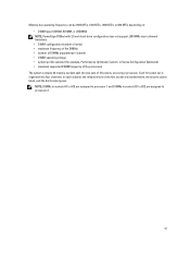
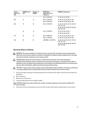
.... 45 Sample Memory Configurations The following tables indicate single-, dual-, and quad-rank DIMMs respectively. Table 1. Memory Configurations-Single Processor System Capacity DIMM Size (in Number of (in GB) GB) DIMMs 2 2 1 4 2 2 8 2 4 12 2 6 16 2 8 4 4 24 2 12 4 6 48 4 12 8 6 96 8 12 16 6 128 16 8 144 16 and 8 10 DIMM ...2R, x4, 1333 MT/s A1, A2, A3, A4, A5, A6, A7, A8, A9, A11 NOTE: 16 GB DIMMs must be installed in slots numbered A1, A2, A3, A4, A5, A6, A7, and A8 and 8 GB DIMMs must be installed in this section. NOTE: 16 GB quad-rank ...
.... 45 Sample Memory Configurations The following tables indicate single-, dual-, and quad-rank DIMMs respectively. Table 1. Memory Configurations-Single Processor System Capacity DIMM Size (in Number of (in GB) GB) DIMMs 2 2 1 4 2 2 8 2 4 12 2 6 16 2 8 4 4 24 2 12 4 6 48 4 12 8 6 96 8 12 16 6 128 16 8 144 16 and 8 10 DIMM ...2R, x4, 1333 MT/s A1, A2, A3, A4, A5, A6, A7, A8, A9, A11 NOTE: 16 GB DIMMs must be installed in slots numbered A1, A2, A3, A4, A5, A6, A7, and A8 and 8 GB DIMMs must be installed in this section. NOTE: 16 GB quad-rank ...
Owner's Manual
Page 46
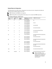
System Capacity DIMM Size (in Number of DIMMs 16 2 8 32 2 16 32 4 8 64 4 16 8 8 96 4 24 8 12 128 8 16 16 8 160 8 20 16 and ...B11 A1, A2, A3, A4, A5, A6, B1, B2, B3, B4, B5, B6 NOTE: 16 GB DIMMs must be installed in slots numbered A1, A2, A3, A4, B1, B2, B3, and B4 and 8 GB DIMMs must be installed in GB) GB) DIMMs 384 32 12... Table 2. Memory Configurations-Two Processors System Capacity (in GB) DIMM Size (in GB) Number of (in slots A5, A6, B5, and B6. A1, A2, A3, A4, A5, A6, A7, A8, A9, A10, A11, A12...
System Capacity DIMM Size (in Number of DIMMs 16 2 8 32 2 16 32 4 8 64 4 16 8 8 96 4 24 8 12 128 8 16 16 8 160 8 20 16 and ...B11 A1, A2, A3, A4, A5, A6, B1, B2, B3, B4, B5, B6 NOTE: 16 GB DIMMs must be installed in slots numbered A1, A2, A3, A4, B1, B2, B3, and B4 and 8 GB DIMMs must be installed in GB) GB) DIMMs 384 32 12... Table 2. Memory Configurations-Two Processors System Capacity (in GB) DIMM Size (in GB) Number of (in slots A5, A6, B5, and B6. A1, A2, A3, A4, A5, A6, A7, A8, A9, A10, A11, A12...
Owner's Manual
Page 47
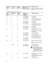
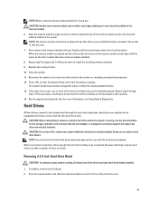
... socket that is not covered by your product documentation, or as authorized in those sockets. 1. System Capacity (in GB) DIMM Size (in GB) Number of DIMMs 256 16 16 384 16 24 32 12 512 32 16 768 32 24 DIMM Rank, Organization, and Frequency 2R, x4, 1600 MT... B5, B6, B7, B8, B9, B10, B11, B12 Removing Memory Modules WARNING: The memory modules are hot to servicing that is not authorized by Dell is not occupied. Handle the memory modules by a certified service technician. Locate the appropriate memory module socket(s). Read and follow the safety instructions that came...
... socket that is not covered by your product documentation, or as authorized in those sockets. 1. System Capacity (in GB) DIMM Size (in GB) Number of DIMMs 256 16 16 384 16 24 32 12 512 32 16 768 32 24 DIMM Rank, Organization, and Frequency 2R, x4, 1600 MT... B5, B6, B7, B8, B9, B10, B11, B12 Removing Memory Modules WARNING: The memory modules are hot to servicing that is not authorized by Dell is not occupied. Handle the memory modules by a certified service technician. Locate the appropriate memory module socket(s). Read and follow the safety instructions that came...
Owner's Manual
Page 49
... align with the hard-drive backplane. For more of this procedure to install the remaining memory modules. 9. Close the system. 11. Doing so can take a number of the hard-drive slot. 49 Align the memory module's edge connector with your system while the hard drive is being formatted. Repeat step 4 through...
... align with the hard-drive backplane. For more of this procedure to install the remaining memory modules. 9. Close the system. 11. Doing so can take a number of the hard-drive slot. 49 Align the memory module's edge connector with your system while the hard drive is being formatted. Repeat step 4 through...
Owner's Manual
Page 56
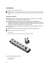
...Many repairs may expose you to a risk of electric shock. Read and follow the safety instructions that is not authorized by Dell is not covered by noting the fan numbers on the cooling fan assembly. NOTE: The procedure for a duration exceeding five minutes. Figure 25. Removing and Installing a ...the product. Exercise utmost care while removing or installing cooling fans. Damage due to servicing that came with a particular fan, the fan number is on may only be done by the online or telephone service and support team. cooling-fan assembly 2. Cooling Fans Your system ...
...Many repairs may expose you to a risk of electric shock. Read and follow the safety instructions that is not authorized by Dell is not covered by noting the fan numbers on the cooling fan assembly. NOTE: The procedure for a duration exceeding five minutes. Figure 25. Removing and Installing a ...the product. Exercise utmost care while removing or installing cooling fans. Damage due to servicing that came with a particular fan, the fan number is on may only be done by the online or telephone service and support team. cooling-fan assembly 2. Cooling Fans Your system ...
Owner's Manual
Page 87
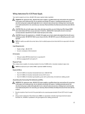
...a -(48-60) V DC supply source that is electrically isolated from size 10 AWG solid or stranded, insulated copper wire NOTE: Use alpha wire part number 3080 or equivalent (65/30 stranding) Required Wires • One UL 10 AWG, 2 m maximum (stranded) black wire [-(48-60) V DC]...by your warranty. Input Requirements • Supply voltage: -(48-60) V DC • Current consumption: 32 A (maximum) Kit Contents • Dell part number 6RYJ9 terminal block or equivalent (1) • #6-32 nut equipped with applicable local or national codes and practices. Ensure that is not covered by your ...
...a -(48-60) V DC supply source that is electrically isolated from size 10 AWG solid or stranded, insulated copper wire NOTE: Use alpha wire part number 3080 or equivalent (65/30 stranding) Required Wires • One UL 10 AWG, 2 m maximum (stranded) black wire [-(48-60) V DC]...by your warranty. Input Requirements • Supply voltage: -(48-60) V DC • Current consumption: 32 A (maximum) Kit Contents • Dell part number 6RYJ9 terminal block or equivalent (1) • #6-32 nut equipped with applicable local or national codes and practices. Ensure that is not covered by your ...
Owner's Manual
Page 93
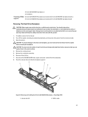
CAUTION: To prevent damage to servicing that is not authorized by Dell is not covered by the online or telephone service and support team. Removing and Installing the 3.5 Inch (x8) SAS/SATA Backplane-PowerEdge R720 1. If installed, remove the front bezel 2. CAUTION: You must remove the... hard drives from the system before removal so that came with the product. 1. Remove the cooling-fan assembly. 6. Read and follow the safety instructions that you must note the number of each...
CAUTION: To prevent damage to servicing that is not authorized by Dell is not covered by the online or telephone service and support team. Removing and Installing the 3.5 Inch (x8) SAS/SATA Backplane-PowerEdge R720 1. If installed, remove the front bezel 2. CAUTION: You must remove the... hard drives from the system before removal so that came with the product. 1. Remove the cooling-fan assembly. 6. Read and follow the safety instructions that you must note the number of each...
Owner's Manual
Page 106
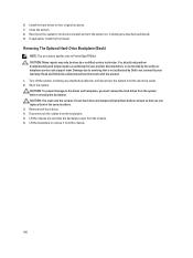
...4. Install the hard drives in your warranty. Close the system. 8. Lift the backplane to PowerEdge R720xd. CAUTION: Many repairs may only be done by the online or telephone service and support...remove the hard drives from the system before removal so that you must note the number of each hard drive and temporarily label them in the same locations. 3. Removing The...including any attached peripherals. 9. Read and follow the safety instructions that is not authorized by Dell is not covered by your product documentation, or as authorized in their original locations. 7. Disconnect...
...4. Install the hard drives in your warranty. Close the system. 8. Lift the backplane to PowerEdge R720xd. CAUTION: Many repairs may only be done by the online or telephone service and support...remove the hard drives from the system before removal so that you must note the number of each hard drive and temporarily label them in the same locations. 3. Removing The...including any attached peripherals. 9. Read and follow the safety instructions that is not authorized by Dell is not covered by your product documentation, or as authorized in their original locations. 7. Disconnect...
Owner's Manual
Page 141
... so on the system's LCD, if the system includes that sensor returns to a normal state. Use the Left and Right buttons to highlight an error number, and press the Select button to select the format in an abbreviated form on , the LCD message is identified by name ("") component... number (""), or location ("bay"). 141 Turn off the system and disconnect it from the display: • Clear the SEL - These messages refer to remove the message ...
... so on the system's LCD, if the system includes that sensor returns to a normal state. Use the Left and Right buttons to highlight an error number, and press the Select button to select the format in an abbreviated form on , the LCD message is identified by name ("") component... number (""), or location ("bay"). 141 Turn off the system and disconnect it from the display: • Clear the SEL - These messages refer to remove the message ...
Owner's Manual
Page 143
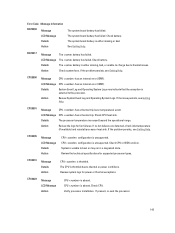
Action Check system fans. LCD Message CPU has a thermal trip. CPU is throttled due to the processor. If the issue persists, see Getting Help. If no fan failures are detected, check inlet temperature (if available) and reinstall processor heat sink. The CPU is absent. The system board battery is external to thermal or power conditions. Details System Event Log and Operating System Logs may run in a degraded state. CPU0001 Message CPU has a thermal trip (over-temperature) event. CPU0005 Message LCD Message Details Action CPU ...
Action Check system fans. LCD Message CPU has a thermal trip. CPU is throttled due to the processor. If the issue persists, see Getting Help. If no fan failures are detected, check inlet temperature (if available) and reinstall processor heat sink. The CPU is absent. The system board battery is external to thermal or power conditions. Details System Event Log and Operating System Logs may run in a degraded state. CPU0001 Message CPU has a thermal trip (over-temperature) event. CPU0005 Message LCD Message Details Action CPU ...


