
Glossary
Page 8
... used. When such devices are video standards for multiple USB-compliant devices, such as password protection. An unregistered (unbuffered) DDR3 memory module. Uninterruptible power supply. A battery-powered unit that automatically supplies power to describe a system that allows a network manager to other hubs or switches without requiring a crossover cable. USB - USB memory...
... used. When such devices are video standards for multiple USB-compliant devices, such as password protection. An unregistered (unbuffered) DDR3 memory module. Uninterruptible power supply. A battery-powered unit that automatically supplies power to describe a system that allows a network manager to other hubs or switches without requiring a crossover cable. USB - USB memory...

Getting Started Guide
Page 12
... the entire system ambient operating range, the inrush current may reach 55 A per power supply for 10 ms or less Batteries System battery CR 2032 3.0-V lithium coin cell RAID battery (optional) 3.7-V lithium ion battery pack Physical Height Width Depth Weight (maximum configuration) Weight (empty) 4.26 cm (1.68 in) 48.24 cm (18.99 in...
... the entire system ambient operating range, the inrush current may reach 55 A per power supply for 10 ms or less Batteries System battery CR 2032 3.0-V lithium coin cell RAID battery (optional) 3.7-V lithium ion battery pack Physical Height Width Depth Weight (maximum configuration) Weight (empty) 4.26 cm (1.68 in) 48.24 cm (18.99 in...
Hardware Owner's Manual
Page 7
... Controller Card 111 Installing the Integrated Storage Controller Card 112 RAID Battery 114 Removing a RAID Battery 114 Installing a RAID Battery 114 Removing the PERC 6/I Battery Cable 114 Installing the PERC 6/I Battery Cable 115 System Memory 116 General Memory Module Installation Guidelines 116... Installing Memory Modules 120 Removing Memory Modules 122 Processors 122 Removing a Processor 122 Installing a Processor 125 System Battery 127 Replacing the System Battery 127 Control Panel Assembly 129 Installing the Control Panel Display Module . . . . 131 Removing the Control ...
... Controller Card 111 Installing the Integrated Storage Controller Card 112 RAID Battery 114 Removing a RAID Battery 114 Installing a RAID Battery 114 Removing the PERC 6/I Battery Cable 114 Installing the PERC 6/I Battery Cable 115 System Memory 116 General Memory Module Installation Guidelines 116... Installing Memory Modules 120 Removing Memory Modules 122 Processors 122 Removing a Processor 122 Installing a Processor 125 System Battery 127 Replacing the System Battery 127 Control Panel Assembly 129 Installing the Control Panel Display Module . . . . 131 Removing the Control ...

Hardware Owner's Manual
Page 8
... Video Subsystem 142 Troubleshooting a USB Device 142 Troubleshooting a Serial I/O Device 143 Troubleshooting a NIC 143 Troubleshooting a Wet System 144 Troubleshooting a Damaged System 145 Troubleshooting the System Battery 146 Troubleshooting Power Supplies 146 Troubleshooting System Cooling Problems 147 Troubleshooting a Fan 148 Troubleshooting System Memory 148 Troubleshooting an Internal SD Card 150 8 Contents
... Video Subsystem 142 Troubleshooting a USB Device 142 Troubleshooting a Serial I/O Device 143 Troubleshooting a NIC 143 Troubleshooting a Wet System 144 Troubleshooting a Damaged System 145 Troubleshooting the System Battery 146 Troubleshooting Power Supplies 146 Troubleshooting System Cooling Problems 147 Troubleshooting a Fan 148 Troubleshooting System Memory 148 Troubleshooting an Internal SD Card 150 8 Contents

Hardware Owner's Manual
Page 24
...to recharge due to thermal issues. LCD Status Messages Code Text E1000 Failsafe voltage error. E1114 Ambient Temp exceeds allowed range. Check battery. allowable range. NOTE: The following table. Table 1-1. To resolve the problem and remove the LCD message, refer to the ...corrective actions in the Simple format. If the problem persists, see "Getting Help." E1211 RAID Controller battery failure. Check battery. Ambient temperature has a See "Troubleshooting reached a point outside of System Cooling the allowed range. See "Setup Menu"to ...
...to recharge due to thermal issues. LCD Status Messages Code Text E1000 Failsafe voltage error. E1114 Ambient Temp exceeds allowed range. Check battery. allowable range. NOTE: The following table. Table 1-1. To resolve the problem and remove the LCD message, refer to the ...corrective actions in the Simple format. If the problem persists, see "Getting Help." E1211 RAID Controller battery failure. Check battery. Ambient temperature has a See "Troubleshooting reached a point outside of System Cooling the allowed range. See "Setup Menu"to ...

Hardware Owner's Manual
Page 36
...power to the system, reduce the hardware configuration or install higher-wattage power supplies, and then restart the system. See "Installing a RAID Battery." Check PSU and config. The system configuration requires more power than 24 24 hours of an abbreviation or acronym used in this table, see... the "Glossary." 36 About Your System Warns predictively that the Allow RAID battery to RAID battery has less than charge to the system, reduce the hardware configuration or install higher-wattage power supplies, and then restart the system...
...power to the system, reduce the hardware configuration or install higher-wattage power supplies, and then restart the system. See "Installing a RAID Battery." Check PSU and config. The system configuration requires more power than 24 24 hours of an abbreviation or acronym used in this table, see... the "Glossary." 36 About Your System Warns predictively that the Allow RAID battery to RAID battery has less than charge to the system, reduce the hardware configuration or install higher-wattage power supplies, and then restart the system...
Hardware Owner's Manual
Page 49
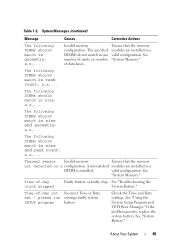
...data lanes. The following DIMMs should match in geometry: x,x,... valid configuration. Check the Time and Date settings. See "System Battery." The specified modules are installed in size and rank count: x,x,... See "System Memory." Causes Corrective Actions Invalid memory Ensure... in size: x,x,... please run settings; If the problem persists, replace the system battery. About Your System 49 Table 1-2. See "Troubleshooting the System Battery." faulty system SETUP program battery. The following DIMMs should match in rank count: x,x,... of ranks, or number ...
...data lanes. The following DIMMs should match in geometry: x,x,... valid configuration. Check the Time and Date settings. See "System Battery." The specified modules are installed in size and rank count: x,x,... See "System Memory." Causes Corrective Actions Invalid memory Ensure... in size: x,x,... please run settings; If the problem persists, replace the system battery. About Your System 49 Table 1-2. See "Troubleshooting the System Battery." faulty system SETUP program battery. The following DIMMs should match in rank count: x,x,... of ranks, or number ...

Hardware Owner's Manual
Page 78
... 5 memory modules (12) 7 SAS backplane 9 optical drive 11 Internal SD Module 8 2 expansion-card riser (2) 4 integrated storage controller card 6 heat sink/processor (2) 8 hard drives (6) 10 RAID battery (PERC only) 12 fans (5 or 6) Removing and Replacing the Optional Front Bezel 1 Unlock the keylock at the left end of the bezel. 2 Lift up on...
... 5 memory modules (12) 7 SAS backplane 9 optical drive 11 Internal SD Module 8 2 expansion-card riser (2) 4 integrated storage controller card 6 heat sink/processor (2) 8 hard drives (6) 10 RAID battery (PERC only) 12 fans (5 or 6) Removing and Replacing the Optional Front Bezel 1 Unlock the keylock at the left end of the bezel. 2 Lift up on...
Hardware Owner's Manual
Page 111
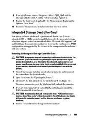
...2 Open the system. To remove a connector, press the latches on the card is not covered by a certified service technician. CAUTION: Disconnecting the RAID battery cable from a PERC card can cause data loss if the "dirty cache" LED on both ends of the connector. 4 If you to set up... controller, disconnect the RAID battery cable from the controller card. Read and follow the safety instructions that provides the integrated storage subsystem for an integrated SAS or PERC controller card that came with your system. The LED indicates that is not authorized by Dell is lit. You should...
...2 Open the system. To remove a connector, press the latches on the card is not covered by a certified service technician. CAUTION: Disconnecting the RAID battery cable from a PERC card can cause data loss if the "dirty cache" LED on both ends of the connector. 4 If you to set up... controller, disconnect the RAID battery cable from the controller card. Read and follow the safety instructions that provides the integrated storage subsystem for an integrated SAS or PERC controller card that came with your system. The LED indicates that is not authorized by Dell is lit. You should...

Hardware Owner's Manual
Page 113
... 1 8 2 3 4 7 6 5 1 SAS data cable connector 3 back card edge guide (black) 5 front card edge guide (blue) 7 SAS data cable 2 integrated storage controller card 4 expansion card riser 1 6 RAID battery connector (PERC only) 8 cable retention clip 5 Close the system. d Attach the connector labeled "SAS A" to connector SAS A on the backplane, and attach the connector labeled...
... 1 8 2 3 4 7 6 5 1 SAS data cable connector 3 back card edge guide (black) 5 front card edge guide (blue) 7 SAS data cable 2 integrated storage controller card 4 expansion card riser 1 6 RAID battery connector (PERC only) 8 cable retention clip 5 Close the system. d Attach the connector labeled "SAS A" to connector SAS A on the backplane, and attach the connector labeled...

Hardware Owner's Manual
Page 114
... that is not authorized by Dell is not covered by your product documentation, or as authorized in the cache is written. 1 Pull back gently on the edge of the chassis next to ensure that came with the optional battery-cached PERC controller card. You...including any attached peripherals. Installing a RAID Battery 1 Connect the battery cable to the connector on the battery. 2 Locate the battery bay on the inner wall of the battery bay and draw out the RAID battery from the battery carrier. 2 Disconnect the cable between the RAID battery and the PERC controller card. See Figure...
... that is not authorized by Dell is not covered by your product documentation, or as authorized in the cache is written. 1 Pull back gently on the edge of the chassis next to ensure that came with the optional battery-cached PERC controller card. You...including any attached peripherals. Installing a RAID Battery 1 Connect the battery cable to the connector on the battery. 2 Locate the battery bay on the inner wall of the battery bay and draw out the RAID battery from the battery carrier. 2 Disconnect the cable between the RAID battery and the PERC controller card. See Figure...

Hardware Owner's Manual
Page 115
...6 Remove the fan bracket. See "Opening the System." 3 Remove the fan bracket. If any other cables from the routing guide. 8 Disconnect the battery cable from the cable clip on page 106. 7 Remove the fan cable from the PERC controller. See "Replacing the Fan Assembly" on , including ... electrical outlet and turn the system on page 107. 9 Close the system. NOTE: Pay attention to the battery connector on the PERC controller. 8 Replace the fan bracket. 3 Disconnect the battery cable from the plastic cable routing guide. See "Removing the Fan Assembly" on the system board nearest PSU ...
...6 Remove the fan bracket. See "Opening the System." 3 Remove the fan bracket. If any other cables from the routing guide. 8 Disconnect the battery cable from the cable clip on page 106. 7 Remove the fan cable from the PERC controller. See "Replacing the Fan Assembly" on , including ... electrical outlet and turn the system on page 107. 9 Close the system. NOTE: Pay attention to the battery connector on the PERC controller. 8 Replace the fan bracket. 3 Disconnect the battery cable from the plastic cable routing guide. See "Removing the Fan Assembly" on the system board nearest PSU ...

Hardware Owner's Manual
Page 127
... operates correctly. Read and follow the safety instructions that is not authorized by your warranty. Installing System Components 127 Replace the battery only with the product. 9 Run the system diagnostics to servicing that came with the same or equivalent type recommended by the... manufacturer. WARNING: There is a danger of a new battery exploding if it is not covered by Dell is incorrectly installed. System Battery Replacing the System Battery CAUTION: Many repairs may only be done by the online or telephone service and support ...
... operates correctly. Read and follow the safety instructions that is not authorized by your warranty. Installing System Components 127 Replace the battery only with the product. 9 Run the system diagnostics to servicing that came with the same or equivalent type recommended by the... manufacturer. WARNING: There is a danger of a new battery exploding if it is not covered by Dell is incorrectly installed. System Battery Replacing the System Battery CAUTION: Many repairs may only be done by the online or telephone service and support ...

Hardware Owner's Manual
Page 128
... into place. 6 Close the system. b Press the battery toward the positive side of the connector. Replacing the System Battery 1 2 3 1 positive side of battery connector 3 negative side of the connector. a Support the battery connector by pressing down firmly on , including any attached ...Components See "Closing the System." 7 Reconnect the system to the battery connector, you must firmly support the connector while installing or removing a battery. 4 Remove the system battery. c Press the battery straight down into the connector until it under the securing tabs at ...
... into place. 6 Close the system. b Press the battery toward the positive side of the connector. Replacing the System Battery 1 2 3 1 positive side of battery connector 3 negative side of the connector. a Support the battery connector by pressing down firmly on , including any attached ...Components See "Closing the System." 7 Reconnect the system to the battery connector, you must firmly support the connector while installing or removing a battery. 4 Remove the system battery. c Press the battery straight down into the connector until it under the securing tabs at ...

Hardware Owner's Manual
Page 129
...consists of the display and slide the blade across the bottom to lift the panel outward. Damage due to servicing that is not authorized by Dell is operating properly. See Figure 3-22. 15 Bend the panel upward to allow access to remove and install either module. Use the following ... 9 Enter the correct time and date in your system. 10 Exit the System Setup program. 8 Enter the System Setup program to confirm that the battery is not covered by your warranty. You should only perform troubleshooting and simple repairs as authorized in the System Setup program's Time and Date fields...
...consists of the display and slide the blade across the bottom to lift the panel outward. Damage due to servicing that is not authorized by Dell is operating properly. See Figure 3-22. 15 Bend the panel upward to allow access to remove and install either module. Use the following ... 9 Enter the correct time and date in your system. 10 Exit the System Setup program. 8 Enter the System Setup program to confirm that the battery is not covered by your warranty. You should only perform troubleshooting and simple repairs as authorized in the System Setup program's Time and Date fields...

Hardware Owner's Manual
Page 139
... the System." 15 Reconnect the system to its electrical outlet and turn the system on the end of riser 1. 11 If applicable, reconnect the RAID battery cable to place the cables under the guide on , including any attached peripherals. 16 Replace the bezel. After connecting the SAS cables to the controller...
... the System." 15 Reconnect the system to its electrical outlet and turn the system on the end of riser 1. 11 If applicable, reconnect the RAID battery cable to place the cables under the guide on , including any attached peripherals. 16 Replace the bezel. After connecting the SAS cables to the controller...

Hardware Owner's Manual
Page 146
... all cables are not correct in the system diagnostics. See "Power Indicator Codes." 146 Troubleshooting Your System See "Replacing the System Battery." Damage due to operate. Operating the system with the product. If the problem is not covered by your product documentation, or ...your warranty. • Memory modules • Hard-drive carriers 4 Ensure that is not authorized by Dell is not resolved by replacing the battery, see "Getting Help." Troubleshooting the System Battery 1 Re-enter the time and date through the System Setup program. Read and follow the safety ...
... all cables are not correct in the system diagnostics. See "Power Indicator Codes." 146 Troubleshooting Your System See "Replacing the System Battery." Damage due to operate. Operating the system with the product. If the problem is not covered by your product documentation, or ...your warranty. • Memory modules • Hard-drive carriers 4 Ensure that is not authorized by Dell is not resolved by replacing the battery, see "Getting Help." Troubleshooting the System Battery 1 Re-enter the time and date through the System Setup program. Read and follow the safety ...

Hardware Owner's Manual
Page 154
3 Restart the system and press the applicable key sequence to servicing that is not authorized by Dell is not covered by your product documentation, or as authorized in your warranty. You should only perform troubleshooting and simple repairs ...as directed by a certified service technician. See "Installing the Integrated Storage Controller Card." 8 If you have a battery-cached PERC controller, ensure that the cables are correct. If the problem persists, see "Getting Help." Damage due to enter the configuration utility program:...
3 Restart the system and press the applicable key sequence to servicing that is not authorized by Dell is not covered by your product documentation, or as authorized in your warranty. You should only perform troubleshooting and simple repairs ...as directed by a certified service technician. See "Installing the Integrated Storage Controller Card." 8 If you have a battery-cached PERC controller, ensure that the cables are correct. If the problem persists, see "Getting Help." Damage due to enter the configuration utility program:...

Hardware Owner's Manual
Page 166
... release lever) memory module slot B5 memory module slot B3 (white release lever) memory module slot B6 7 CPU2 processor socket 2 8 CPU1 processor socket 1 9 BATTERY connector for the 3.0-V coin battery 10 FAN_MODn fan module power connector (6) 11 BP_PWR SAS backplane power cable connector 12 CTRL_USB control panel USB interface cable connector 13 DVD_PWR...
... release lever) memory module slot B5 memory module slot B3 (white release lever) memory module slot B6 7 CPU2 processor socket 2 8 CPU1 processor socket 1 9 BATTERY connector for the 3.0-V coin battery 10 FAN_MODn fan module power connector (6) 11 BP_PWR SAS backplane power cable connector 12 CTRL_USB control panel USB interface cable connector 13 DVD_PWR...
Hardware Owner's Manual
Page 176
... disconnected while the system is expressed as mice and keyboards. When such devices are connected in a series, you must support the resolution. 176 Glossary UDIMM - A battery-powered unit that plugs into the system board or may need to your monitor must install the appropriate video drivers and your system in the...
... disconnected while the system is expressed as mice and keyboards. When such devices are connected in a series, you must support the resolution. 176 Glossary UDIMM - A battery-powered unit that plugs into the system board or may need to your monitor must install the appropriate video drivers and your system in the...

