EMC Boot Optimized Server Storage-S1 Users Guide
Page 6
...6.7 NOTE: For the latest list of supported operating systems and driver installation instructions, see the Drivers and Downloads section at www.dell.com/operatingsystemmanuals. • Update the BOSS-S1 controller • Update the BOSS-S1 firmware • Firmware update using an ... • Related documentation Supported operating systems The BOSS-S1 card supports the following PowerEdge systems support the BOSS-S1 adapter card: • PowerEdge C4140 • PowerEdge C6525 • PowerEdge R240 • PowerEdge R340 • PowerEdge R440 • PowerEdge R540 6 Overview
...6.7 NOTE: For the latest list of supported operating systems and driver installation instructions, see the Drivers and Downloads section at www.dell.com/operatingsystemmanuals. • Update the BOSS-S1 controller • Update the BOSS-S1 firmware • Firmware update using an ... • Related documentation Supported operating systems The BOSS-S1 card supports the following PowerEdge systems support the BOSS-S1 adapter card: • PowerEdge C4140 • PowerEdge C6525 • PowerEdge R240 • PowerEdge R340 • PowerEdge R440 • PowerEdge R540 6 Overview
EMC PowerEdge RAID Controller S140 Users Guide
Page 10
...; PowerEdge R240 • PowerEdge R340 • PowerEdge R440 • PowerEdge R540 • PowerEdge R640 • PowerEdge R740 • PowerEdge R740xd • PowerEdge R740xd2 • PowerEdge R840 • PowerEdge R940 • PowerEdge R940xa • PowerEdge R6415 • PowerEdge R7425 • PowerEdge R7415 • PowerEdge T140 • PowerEdge T340 • PowerEdge T440 • PowerEdge T640 • PowerEdge XE2420 Supported physical disks The PERC S140 controller supports the following operating systems: NOTE: See Dell...
...; PowerEdge R240 • PowerEdge R340 • PowerEdge R440 • PowerEdge R540 • PowerEdge R640 • PowerEdge R740 • PowerEdge R740xd • PowerEdge R740xd2 • PowerEdge R840 • PowerEdge R940 • PowerEdge R940xa • PowerEdge R6415 • PowerEdge R7425 • PowerEdge R7415 • PowerEdge T140 • PowerEdge T340 • PowerEdge T440 • PowerEdge T640 • PowerEdge XE2420 Supported physical disks The PERC S140 controller supports the following operating systems: NOTE: See Dell...
EMC Installation and Service Manual
Page 1
A07 Dell EMC PowerEdge R540 Installation and Service Manual Regulatory Model: E46S Series Regulatory Type: E46S001 July 2020 Rev.
A07 Dell EMC PowerEdge R540 Installation and Service Manual Regulatory Model: E46S Series Regulatory Type: E46S001 July 2020 Rev.
EMC Installation and Service Manual
Page 3
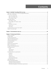
Contents Chapter 1: Dell EMC PowerEdge R540 overview 8 Supported configurations for the PowerEdge R540 system 8 Front view of the system...9 Left control panel view...11 Right control panel view...14 Drive indicator codes...15 Back panel features...16 NIC ...
Contents Chapter 1: Dell EMC PowerEdge R540 overview 8 Supported configurations for the PowerEdge R540 system 8 Front view of the system...9 Left control panel view...11 Right control panel view...14 Drive indicator codes...15 Back panel features...16 NIC ...
EMC Installation and Service Manual
Page 8
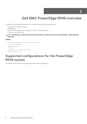
1 Dell EMC PowerEdge R540 overview The Dell EMC PowerEdge R540 system is a 2U, dual socket rack system that supports up to as drives in this document, unless specified otherwise. Topics: • Supported configurations for the PowerEdge R540 system • Front view of the system • Back panel features • LCD panel &#...drives or solid-state drives NOTE: All instances of your system • System information label Supported configurations for the PowerEdge R540 system The Dell EMC PowerEdge R540 system supports the following configurations: 8 Dell EMC PowerEdge R540 overview
1 Dell EMC PowerEdge R540 overview The Dell EMC PowerEdge R540 system is a 2U, dual socket rack system that supports up to as drives in this document, unless specified otherwise. Topics: • Supported configurations for the PowerEdge R540 system • Front view of the system • Back panel features • LCD panel &#...drives or solid-state drives NOTE: All instances of your system • System information label Supported configurations for the PowerEdge R540 system The Dell EMC PowerEdge R540 system supports the following configurations: 8 Dell EMC PowerEdge R540 overview
EMC Installation and Service Manual
Page 9
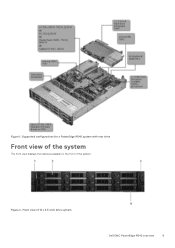
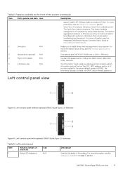
Figure 2. Front view of the system. Figure 1. Supported configurations for a PowerEdge R540 system with rear drive Front view of the system The front view displays the features available on the front of 12 x 3.5-inch drive system Dell EMC PowerEdge R540 overview 9
Figure 2. Front view of the system. Figure 1. Supported configurations for a PowerEdge R540 system with rear drive Front view of the system The front view displays the features available on the front of 12 x 3.5-inch drive system Dell EMC PowerEdge R540 overview 9
EMC Installation and Service Manual
Page 10
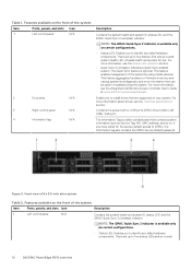
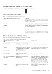
...devices. There are up to identify any failed hardware components. For more information about drives, see the Integrated Dell Remote Access Controller User's Guide at www.dell.com/poweredgemanuals. Figure 3. NOTE: The iDRAC Quick Sync 2 indicator is available only on your system. This...configurations. • Status LED: Enables you have opted for the secure default access to five status LEDs and an overall 10 Dell EMC PowerEdge R540 overview For more information, see the Technical specifications section. NOTE: The iDRAC Quick Sync 2 indicator is available only on . This...
...devices. There are up to identify any failed hardware components. For more information about drives, see the Integrated Dell Remote Access Controller User's Guide at www.dell.com/poweredgemanuals. Figure 3. NOTE: The iDRAC Quick Sync 2 indicator is available only on your system. This...configurations. • Status LED: Enables you have opted for the secure default access to five status LEDs and an overall 10 Dell EMC PowerEdge R540 overview For more information, see the Technical specifications section. NOTE: The iDRAC Quick Sync 2 indicator is available only on . This...
EMC Installation and Service Manual
Page 11
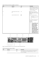
... LED indicators on the front of the system (continued) Item Ports, panels, and slots Icon Description system health LED (Chassis health and system ID) bar. Dell EMC PowerEdge R540 overview 11 For more information, see the Status LED indicators section. • Quick Sync 2 (wireless): Indicates a Quick Sync enabled system. For more information, see...
... LED indicators on the front of the system (continued) Item Ports, panels, and slots Icon Description system health LED (Chassis health and system ID) bar. Dell EMC PowerEdge R540 overview 11 For more information, see the Status LED indicators section. • Quick Sync 2 (wireless): Indicates a Quick Sync enabled system. For more information, see...
EMC Installation and Service Manual
Page 12
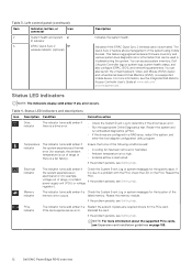
...that none of the system using mobile devices. For more information about the supported PCIe cards, see the Integrated Dell Remote Access Controller User's Guide at www.dell.com/ poweredgemanuals . If the problem persists, see Getting help . If the system experiences an it is a... the virtual Keyboard, Video, and Mouse (KVM) viewer and virtual Kernel based Virtual Machine (KVM), on page 109. 12 Dell EMC PowerEdge R540 overview Temperature indicator The indicator turns solid amber if the system experiences a thermal error (for example, the ambient temperature is obstructed...
...that none of the system using mobile devices. For more information about the supported PCIe cards, see the Integrated Dell Remote Access Controller User's Guide at www.dell.com/ poweredgemanuals . If the problem persists, see Getting help . If the system experiences an it is a... the virtual Keyboard, Video, and Mouse (KVM) viewer and virtual Kernel based Virtual Machine (KVM), on page 109. 12 Dell EMC PowerEdge R540 overview Temperature indicator The indicator turns solid amber if the system experiences a thermal error (for example, the ambient temperature is obstructed...
EMC Installation and Service Manual
Page 13
... the indicator continues to be disabled by iDRAC. Blinking blue Indicates that the iDRAC Quick Sync 2 then turns off . Dell EMC PowerEdge R540 overview 13 Figure 6. Blinks white rapidly Indicates data transfer activity. Blinks white five times rapidly and Indicates that the system ... Sync 2 feature is disabled. Blinking amber Indicates that the system is turned on the bezel, for 14th Generation Dell EMC PowerEdge Servers at www.dell.com/openmanagemanuals > OpenManage Server Administrator. If the problem persists, see the Event and Error Message Reference Guide for ...
... the indicator continues to be disabled by iDRAC. Blinking blue Indicates that the iDRAC Quick Sync 2 then turns off . Dell EMC PowerEdge R540 overview 13 Figure 6. Blinks white rapidly Indicates data transfer activity. Blinks white five times rapidly and Indicates that the system ... Sync 2 feature is disabled. Blinking amber Indicates that the system is turned on the bezel, for 14th Generation Dell EMC PowerEdge Servers at www.dell.com/openmanagemanuals > OpenManage Server Administrator. If the problem persists, see the Event and Error Message Reference Guide for ...
EMC Installation and Service Manual
Page 14
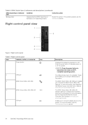
Right control panel view Figure 7. For more information, see the Technical specifications section. 14 Dell EMC PowerEdge R540 overview Enables you to connect USB devices to the system. NOTE: Press the power button to access the iDRAC Direct (Micro-AB... code Corrective action Blinking amber Indicates that the iDRAC Direct port is not responding properly. For more information, see the Integrated Dell Remote Access Controller User's Guide at www.dell.com/poweredgemanuals. For more information, see the Getting help section. If the problem persists, see Integrated...
Right control panel view Figure 7. For more information, see the Technical specifications section. 14 Dell EMC PowerEdge R540 overview Enables you to connect USB devices to the system. NOTE: Press the power button to access the iDRAC Direct (Micro-AB... code Corrective action Blinking amber Indicates that the iDRAC Direct port is not responding properly. For more information, see the Integrated Dell Remote Access Controller User's Guide at www.dell.com/poweredgemanuals. For more information, see the Getting help section. If the problem persists, see Integrated...
EMC Installation and Service Manual
Page 15
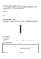
... indicator and a status LED indicator. Drive activity LED indicator 2. NOTE: The drive status indicator remains off until all drives are not ready for removal. Dell EMC PowerEdge R540 overview 15 Flashing green (on . The activity LED indicator indicates whether the drive is connected. The indicators provide information about the current status of the...
... indicator and a status LED indicator. Drive activity LED indicator 2. NOTE: The drive status indicator remains off until all drives are not ready for removal. Dell EMC PowerEdge R540 overview 15 Flashing green (on . The activity LED indicator indicates whether the drive is connected. The indicators provide information about the current status of the...
EMC Installation and Service Manual
Page 16
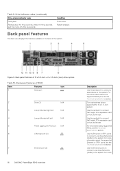
... Icon 1 Serial port 2 Drive (2) N/A 3 Low profile riser right slot N/A 4 Low profile riser left slot N/A 5 Power supply unit (PSU) (2) N/A 6 LOM riser port (2) 7 Ethernet port (2) 16 Dell EMC PowerEdge R540 overview Description Use the serial port to connect a serial device to the system. Back panel features of 12 x 3.5-inch + 2 x 3.5-inch (rear) drive system Table 10...
... Icon 1 Serial port 2 Drive (2) N/A 3 Low profile riser right slot N/A 4 Low profile riser left slot N/A 5 Power supply unit (PSU) (2) N/A 6 LOM riser port (2) 7 Ethernet port (2) 16 Dell EMC PowerEdge R540 overview Description Use the serial port to connect a serial device to the system. Back panel features of 12 x 3.5-inch + 2 x 3.5-inch (rear) drive system Table 10...
EMC Installation and Service Manual
Page 17
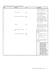
..., press and hold the system ID button (for more than five seconds) to securely access the embedded iDRAC on or off. Back panel features of R540 (continued) Item Features Icon 8 USB 3.0 port (2) 9 iDRAC9 dedicated network port 10 VGA port 11 System status indicator cable N/A port 12 System identification button Description information... management network, see the Technical specifications section. Table 10. These ports are 4-pin, USB 3.0-compliant. Use the VGA port to connect a display to the system. Dell EMC PowerEdge R540 overview 17
..., press and hold the system ID button (for more than five seconds) to securely access the embedded iDRAC on or off. Back panel features of R540 (continued) Item Features Icon 8 USB 3.0 port (2) 9 iDRAC9 dedicated network port 10 VGA port 11 System status indicator cable N/A port 12 System identification button Description information... management network, see the Technical specifications section. Table 10. These ports are 4-pin, USB 3.0-compliant. Use the VGA port to connect a display to the system. Dell EMC PowerEdge R540 overview 17
EMC Installation and Service Manual
Page 18
...riser slot N/A 4 Power supply unit (PSU) (2) N/A 5 LOM riser port (2) 6 Ethernet port (2) 7 USB 3.0 port (2) 8 iDRAC9 dedicated network port 18 Dell EMC PowerEdge R540 overview Description Use the serial port to connect a serial device to securely access the embedded iDRAC on full height riser. Back panel features of 12.... These ports are 4-pin, USB 3.0-compliant. For more information about supported PSUs, see the Integrated Dell Remote Access Controller User's Guide at www.dell.com/ poweredgemanuals. Two optional rear drives supported for 12 x 3.5 inch system.
...riser slot N/A 4 Power supply unit (PSU) (2) N/A 5 LOM riser port (2) 6 Ethernet port (2) 7 USB 3.0 port (2) 8 iDRAC9 dedicated network port 18 Dell EMC PowerEdge R540 overview Description Use the serial port to connect a serial device to securely access the embedded iDRAC on full height riser. Back panel features of 12.... These ports are 4-pin, USB 3.0-compliant. For more information about supported PSUs, see the Integrated Dell Remote Access Controller User's Guide at www.dell.com/ poweredgemanuals. Two optional rear drives supported for 12 x 3.5 inch system.
EMC Installation and Service Manual
Page 19
... indicator cable N/A port 11 System identification button Description Use the VGA port to connect a display to the system. Dell EMC PowerEdge R540 overview 19 Table 11. For more information about the supported VGA port, see the Technical specifications section. Figure 11. Back ...panel features of R540 Item Features Icon 1 Serial port Description Use the serial port to connect a serial device to the system. ...
... indicator cable N/A port 11 System identification button Description Use the VGA port to connect a display to the system. Dell EMC PowerEdge R540 overview 19 Table 11. For more information about the supported VGA port, see the Technical specifications section. Figure 11. Back ...panel features of R540 Item Features Icon 1 Serial port Description Use the serial port to connect a serial device to the system. ...
EMC Installation and Service Manual
Page 20
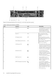
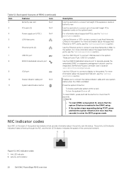
... back of the system has indicators that the system ID button is flowing through the NIC, and the link LED indicator indicates the speed of R540 (continued) Item Features Icon 2 Butterfly riser slot N/A 3 PCIe slot (3) N/A 4 Power supply unit (PSU) N/A 5 LOM riser ports 6 Ethernet ports (2) 7 USB 3.0 port 8 iDRAC9 dedicated network port 9 VGA... responding during POST, press and hold the button for more information about supported PSUs, see the Technical specifications section. Figure 12. activity LED indicator 20 Dell EMC PowerEdge R540 overview
... back of the system has indicators that the system ID button is flowing through the NIC, and the link LED indicator indicates the speed of R540 (continued) Item Features Icon 2 Butterfly riser slot N/A 3 PCIe slot (3) N/A 4 Power supply unit (PSU) N/A 5 LOM riser ports 6 Ethernet ports (2) 7 USB 3.0 port 8 iDRAC9 dedicated network port 9 VGA... responding during POST, press and hold the button for more information about supported PSUs, see the Technical specifications section. Figure 12. activity LED indicator 20 Dell EMC PowerEdge R540 overview
EMC Installation and Service Manual
Page 21
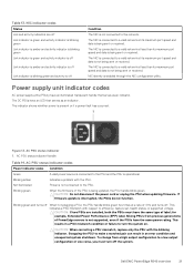
...sent or received. CAUTION: Do not disconnect the power cord or unplug the PSU when updating firmware. Blinking green and turns off . Dell EMC PowerEdge R540 overview 21 The NIC is operational. Power supply unit indicator codes AC power supply units (PSUs) have the same power rating. Not ...shutdown. The NIC is being updated, the PSU handle blinks green. This indicates a PSU mismatch with respect to a valid network at a rate of PowerEdge servers is present or if a power fault has occurred. AC PSU status indicator 1. Swapping the PSU to make a matched pair can result in ...
...sent or received. CAUTION: Do not disconnect the power cord or unplug the PSU when updating firmware. Blinking green and turns off . Dell EMC PowerEdge R540 overview 21 The NIC is operational. Power supply unit indicator codes AC power supply units (PSUs) have the same power rating. Not ...shutdown. The NIC is being updated, the PSU handle blinks green. This indicates a PSU mismatch with respect to a valid network at a rate of PowerEdge servers is present or if a power fault has occurred. AC PSU status indicator 1. Swapping the PSU to make a matched pair can result in ...
EMC Installation and Service Manual
Page 22
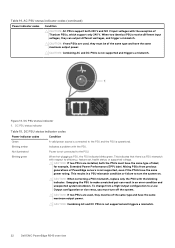
... is not supported and triggers a mismatch. Table 14. Not illuminated Power is not supported and triggers a mismatch. 22 Dell EMC PowerEdge R540 overview CAUTION: If two PSUs are installed, both 240 V and 120 V input voltages with the PSU. This results in an error condition and unexpected system ...
... is not supported and triggers a mismatch. Table 14. Not illuminated Power is not supported and triggers a mismatch. 22 Dell EMC PowerEdge R540 overview CAUTION: If two PSUs are installed, both 240 V and 120 V input voltages with the PSU. This results in an error condition and unexpected system ...
EMC Installation and Service Manual
Page 23
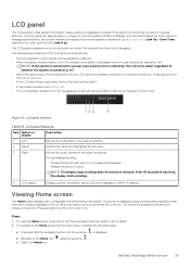
... Home screen, press one -step increments. Press and hold the right button to increase scrolling speed. • Release the button to stop. Dell EMC PowerEdge R540 overview 23 LCD panel The LCD panel provides system information, status, and error messages to the Home icon c. NOTE: If the system is displayed...LCD messaging is released. During message scrolling: • Press and hold the navigation button until the up arrow is connected to qrl.dell.com > Look Up > Error Code, type the error code, and then click Look it . Figure 15. Steps 1. For information about the system...
... Home screen, press one -step increments. Press and hold the right button to increase scrolling speed. • Release the button to stop. Dell EMC PowerEdge R540 overview 23 LCD panel The LCD panel provides system information, status, and error messages to the Home icon c. NOTE: If the system is displayed...LCD messaging is released. During message scrolling: • Press and hold the navigation button until the up arrow is connected to qrl.dell.com > Look Up > Error Code, type the error code, and then click Look it . Figure 15. Steps 1. For information about the system...


