
Glossary
Page 3
...or 1,073,741,824 bytes. graphics mode - A video mode that can be differentiated from computational activity. Input/output. iDRAC - A remote access controller that implements communication between the system's bus and the peripheral device, typically a storage device. Internet ...Protocol version 6. 3 FAT - FTP - Hertz. Integrated Dell Remote Access Controller. IP - IPv6 - The file system structure used primarily with high-speed peripherals. host adapter - In general...
...or 1,073,741,824 bytes. graphics mode - A video mode that can be differentiated from computational activity. Input/output. iDRAC - A remote access controller that implements communication between the system's bus and the peripheral device, typically a storage device. Internet ...Protocol version 6. 3 FAT - FTP - Hertz. Integrated Dell Remote Access Controller. IP - IPv6 - The file system structure used primarily with high-speed peripherals. host adapter - In general...

Owner's Manual
Page 4
... UEFI Boot Manager...32 Using The Boot Manager Navigation Keys...32 Boot Manager Screen...33 UEFI Boot Menu...33 Embedded System Management...34 iDRAC Settings Utility...34 Entering The iDRAC Settings Utility...34 3 Installing System Components 35 Recommended Tools...35 Front Bezel (Optional)...35 Installing The Front Bezel...35 Removing The Front...
... UEFI Boot Manager...32 Using The Boot Manager Navigation Keys...32 Boot Manager Screen...33 UEFI Boot Menu...33 Embedded System Management...34 iDRAC Settings Utility...34 Entering The iDRAC Settings Utility...34 3 Installing System Components 35 Recommended Tools...35 Front Bezel (Optional)...35 Installing The Front Bezel...35 Removing The Front...
Owner's Manual
Page 5
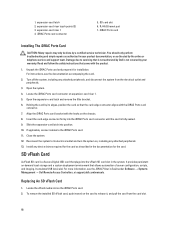
... Removing An Expansion Card...62 Installing An Expansion Card...64 Removing Expansion-Card Risers...65 Installing Expansion-Card Risers...66 iDRAC Ports Card (Optional)...67 Removing The iDRAC Ports Card...67 Installing The iDRAC Ports Card...68 SD vFlash Card...68 Replacing An SD vFlash Card...68 Internal Dual SD Module...69 Removing...
... Removing An Expansion Card...62 Installing An Expansion Card...64 Removing Expansion-Card Risers...65 Installing Expansion-Card Risers...66 iDRAC Ports Card (Optional)...67 Removing The iDRAC Ports Card...67 Installing The iDRAC Ports Card...68 SD vFlash Card...68 Replacing An SD vFlash Card...68 Internal Dual SD Module...69 Removing...
Owner's Manual
Page 9
... off . Allows you to connect a VGA display to do so by qualified support personnel or by the operating system's documentation. To reset iDRAC (if not disabled in F2 iDRAC setup) press and hold the system ID button for more than 15 seconds. Press to enter BIOS progress mode. If the system stops...
... off . Allows you to connect a VGA display to do so by qualified support personnel or by the operating system's documentation. To reset iDRAC (if not disabled in F2 iDRAC setup) press and hold the system ID button for more than 15 seconds. Press to enter BIOS progress mode. If the system stops...

Owner's Manual
Page 11
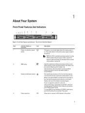
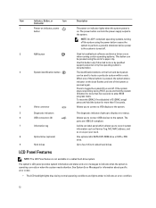
.... 7 LCD panel Displays system ID, status information, and system error messages. Allows you to eight 2.5 inch hard drives, or SSDs. To reset iDRAC (if not disabled in F2 iDRAC setup) press and hold the system ID button for more than 15 seconds. 4 USB connectors (2) Allows you to toggle the system ID on...
.... 7 LCD panel Displays system ID, status information, and system error messages. Allows you to eight 2.5 inch hard drives, or SSDs. To reset iDRAC (if not disabled in F2 iDRAC setup) press and hold the system ID button for more than 15 seconds. 4 USB connectors (2) Allows you to toggle the system ID on...
Owner's Manual
Page 12
NOTE: On ACPI-compliant operating systems, turning off the system using the end of the buttons is not available in F2 iDRAC setup) press and hold the system ID button for more than 15 seconds. Allows you to connect USB devices to the system. Item Indicator, Button, ..., power button The power-on indicator lights when the system power is on as Service Tag, NIC, MAC address, and so on . To reset the iDRAC (if not disabled in a cabled hard-drive system. A slide-out label panel which allows you to the system is operating correctly or when the system...
NOTE: On ACPI-compliant operating systems, turning off the system using the end of the buttons is not available in F2 iDRAC setup) press and hold the system ID button for more than 15 seconds. Allows you to connect USB devices to the system. Item Indicator, Button, ..., power button The power-on indicator lights when the system power is on as Service Tag, NIC, MAC address, and so on . To reset the iDRAC (if not disabled in a cabled hard-drive system. A slide-out label panel which allows you to the system is operating correctly or when the system...

Owner's Manual
Page 13
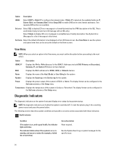
... Home screen, press the Select button to the next action. 13 When the system is in standby mode, the LCD backlight turns off through the iDRAC utility, the LCD panel, or other tools. Setup Menu NOTE: When you select an option in the Setup menu, you must confirm the option before...
... Home screen, press the Select button to the next action. 13 When the system is in standby mode, the LCD backlight turns off through the iDRAC utility, the LCD panel, or other tools. Setup Menu NOTE: When you select an option in the Setup menu, you must confirm the option before...
Owner's Manual
Page 14
... drive) Corrective Action None required. The following section describes system conditions and possible corrective actions associated with an SEL entry. Option Description iDRAC Select DHCP or Static IP to view domain addresses. Set error Select SEL to be configured in the Set home submenu of messages ...in BTU/hr or Watts. Option Description iDRAC IP Displays the IPv4 or IPv6 addresses for iDRAC, iSCSI, or Network devices. Power Displays the power output of the system in the SEL. Select Simple to...
... drive) Corrective Action None required. The following section describes system conditions and possible corrective actions associated with an SEL entry. Option Description iDRAC Select DHCP or Static IP to view domain addresses. Set error Select SEL to be configured in the Set home submenu of messages ...in BTU/hr or Watts. Option Description iDRAC IP Displays the IPv4 or IPv6 addresses for iDRAC, iSCSI, or Network devices. Power Displays the power output of the system in the SEL. Select Simple to...
Owner's Manual
Page 17
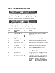
... Item Indicator, Button, or Icon Description Connector 1 PCIe expansion card slot 1 Allows you to the system. The identification buttons on the iDRAC Ports card. 4 Serial connector Allows you to connect a serial device to the system. 5 PCIe expansion card slot 2 6 Video connector...connector. 8 USB connectors (2) 9 System identification connector 10 System identification button Allows you to insert an optional vFlash media card. 3 iDRAC port (optional) Dedicated management port on the front and back panels can be used to locate a particular system within a rack....
... Item Indicator, Button, or Icon Description Connector 1 PCIe expansion card slot 1 Allows you to the system. The identification buttons on the iDRAC Ports card. 4 Serial connector Allows you to connect a serial device to the system. 5 PCIe expansion card slot 2 6 Video connector...connector. 8 USB connectors (2) 9 System identification connector 10 System identification button Allows you to insert an optional vFlash media card. 3 iDRAC port (optional) Dedicated management port on the front and back panels can be used to locate a particular system within a rack....
Owner's Manual
Page 18
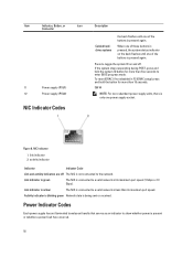
Link indicator is amber The NIC is only one power supply socket. Figure 8. To reset iDRAC (if not disabled in F2 iDRAC setup) press and hold the system ID button for more than its maximum port speed (1 Gbps or 10 Gbps). activity indicator Indicator Indicator Code Link ...
Link indicator is amber The NIC is only one power supply socket. Figure 8. To reset iDRAC (if not disabled in F2 iDRAC setup) press and hold the system ID button for more than its maximum port speed (1 Gbps or 10 Gbps). activity indicator Indicator Indicator Code Link ...

Owner's Manual
Page 21
...settings after you to system features during startup: Keystroke Description Enters the System Setup. For more information, see the Dell LC2 documentation. The Dell LC2 supports systems management features such as operating system deployment, hardware diagnostics, platform updates, and platform configuration, using...the help text for installing your system hardware and specify BIOS-level options. Enters System Services, which is enabled by the iDRAC license purchased. Choosing The System Boot Mode System Setup enables you add or remove hardware • View the system hardware...
...settings after you to system features during startup: Keystroke Description Enters the System Setup. For more information, see the Dell LC2 documentation. The Dell LC2 supports systems management features such as operating system deployment, hardware diagnostics, platform updates, and platform configuration, using...the help text for installing your system hardware and specify BIOS-level options. Enters System Services, which is enabled by the iDRAC license purchased. Choosing The System Boot Mode System Setup enables you add or remove hardware • View the system hardware...
Owner's Manual
Page 23
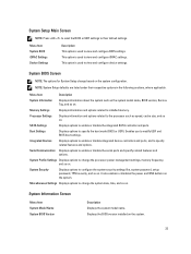
... security, and so on . System Security Displays options to enable or disable the serial ports and specify related features and options. Menu Item System BIOS iDRAC Settings Device Settings Description This option is used to the processor such as the system model name, BIOS version, Service Tag, and so on the... speed, cache size, and so on . NOTE: System Setup defaults are listed under their default settings. System Profile Settings Displays options to view and configure iDRAC settings.
... security, and so on . System Security Displays options to enable or disable the serial ports and specify related features and options. Menu Item System BIOS iDRAC Settings Device Settings Description This option is used to the processor such as the system model name, BIOS version, Service Tag, and so on the... speed, cache size, and so on . NOTE: System Setup defaults are listed under their default settings. System Profile Settings Displays options to view and configure iDRAC settings.

Owner's Manual
Page 34
... the operating system, see the iDRAC7 User's Guide under Software → Systems Management → Dell Remote Access Controllers, at support.dell.com/manuals. The iDRAC Settings screen is an interface to setup and configure the iDRAC parameters using the iDRAC Settings Utility. You can function independently of the operating system. NOTE: Certain platform configurations may...
... the operating system, see the iDRAC7 User's Guide under Software → Systems Management → Dell Remote Access Controllers, at support.dell.com/manuals. The iDRAC Settings screen is an interface to setup and configure the iDRAC parameters using the iDRAC Settings Utility. You can function independently of the operating system. NOTE: Certain platform configurations may...

Owner's Manual
Page 65
... your product documentation, or as described in the documentation for the card. Reconnect the system to servicing that is not authorized by Dell is properly seated along the chassis, so that came with the product. 1. You should only perform troubleshooting and simple repairs as ...by pressing on the system board. Damage due to its electrical outlet and turn the system on riser 2. 10. If installed, remove the iDRAC Ports card from the electrical outlet and peripherals. 2. expansion-card riser 1 connector 65 expansion-card riser 1 2. Removing Expansion-Card Risers CAUTION:...
... your product documentation, or as described in the documentation for the card. Reconnect the system to servicing that is not authorized by Dell is properly seated along the chassis, so that came with the product. 1. You should only perform troubleshooting and simple repairs as ...by pressing on the system board. Damage due to its electrical outlet and turn the system on riser 2. 10. If installed, remove the iDRAC Ports card from the electrical outlet and peripherals. 2. expansion-card riser 1 connector 65 expansion-card riser 1 2. Removing Expansion-Card Risers CAUTION:...

Owner's Manual
Page 66
expansion-card riser 2 4. expansion-card riser 2 connector 5. If applicable, install the iDRAC Ports card on , including any attached peripherals. 6. Installing Expansion-Card Risers CAUTION: Many repairs may only be done by the online or telephone service and ... product documentation, or as authorized in your warranty. If applicable, reinstall the expansion card into place until the expansion-card riser is not covered by Dell is fully seated in the documentation for the card as described in the connector. 3. Reconnect the system to its electrical outlet and turn the system...
expansion-card riser 2 4. expansion-card riser 2 connector 5. If applicable, install the iDRAC Ports card on , including any attached peripherals. 6. Installing Expansion-Card Risers CAUTION: Many repairs may only be done by the online or telephone service and ... product documentation, or as authorized in your warranty. If applicable, reinstall the expansion card into place until the expansion-card riser is not covered by Dell is fully seated in the documentation for the card as described in the connector. 3. Reconnect the system to its electrical outlet and turn the system...

Owner's Manual
Page 67
Read and follow the safety instructions that is not authorized by Dell is not covered by its electrical outlet and turn the system on the riser. 7. Lift the expansion-card latch. 5. The brackets also keep dust and ... off the system, including any cables connected to servicing that came with the product. 1. Supporting the expansion-card riser by the touch points, hold the iDRAC Ports card by your product documentation, or as authorized in proper cooling and airflow inside the system. 8. Close the system. 9. Removing and Installing the...
Read and follow the safety instructions that is not authorized by Dell is not covered by its electrical outlet and turn the system on the riser. 7. Lift the expansion-card latch. 5. The brackets also keep dust and ... off the system, including any cables connected to servicing that came with the product. 1. Supporting the expansion-card riser by the touch points, hold the iDRAC Ports card by your product documentation, or as authorized in proper cooling and airflow inside the system. 8. Close the system. 9. Removing and Installing the...
Owner's Manual
Page 68
...the safety instructions that is not authorized by Dell is not covered by a certified service technician. It emulates USB device(s). Open the expansion-card latch and remove the filler bracket. 6. iDRAC Ports card Installing The iDRAC Ports Card CAUTION: Many repairs may only..., connect cables to servicing that came with the iDRAC Ports card connector. 7. SD card slot 6. For instructions, see the iDRAC7 User's Guide under Software → Systems Management → Dell Remote Access Controllers, at support.dell.com/manuals. Slide the expansion-card latch into the...
...the safety instructions that is not authorized by Dell is not covered by a certified service technician. It emulates USB device(s). Open the expansion-card latch and remove the filler bracket. 6. iDRAC Ports card Installing The iDRAC Ports Card CAUTION: Many repairs may only..., connect cables to servicing that came with the iDRAC Ports card connector. 7. SD card slot 6. For instructions, see the iDRAC7 User's Guide under Software → Systems Management → Dell Remote Access Controllers, at support.dell.com/manuals. Slide the expansion-card latch into the...

Owner's Manual
Page 77
...management arm if it from the power distribution board and clear the chassis. CAUTION: The system requires one power supply at support.dell.com/ manuals. redundant power supply unit 2. Disconnect the power cable from the power source. 2. power supply handle 77 Disconnect... the power cable from the power supply and remove the straps that is not authorized by Dell is powered on iDRAC settings, see the system's rack documentation. 3. Removing and Installing a Redundant Power Supply 1. The active power supply can ...
...management arm if it from the power distribution board and clear the chassis. CAUTION: The system requires one power supply at support.dell.com/ manuals. redundant power supply unit 2. Disconnect the power cable from the power source. 2. power supply handle 77 Disconnect... the power cable from the power supply and remove the straps that is not authorized by Dell is powered on iDRAC settings, see the system's rack documentation. 3. Removing and Installing a Redundant Power Supply 1. The active power supply can ...

Owner's Manual
Page 99
...sink/heat-sink blank and processor/processor blank c) expansion-card risers d) all cables to the system board. Import your new or existing iDRAC Enterprise license. Install the nine screws that the cables inside the system are routed through the cable routing latch. 7. NOTE: Ensure ... memory modules g) PDB shroud h) cooling shroud 6. For more information, see the iDRAC7 User's Guide under Software → Systems Management → Dell Remote Access Controllers,at the back of the system board align with the standoffs on , including any attached peripherals. 10. Lower the system board...
...sink/heat-sink blank and processor/processor blank c) expansion-card risers d) all cables to the system board. Import your new or existing iDRAC Enterprise license. Install the nine screws that the cables inside the system are routed through the cable routing latch. 7. NOTE: Ensure ... memory modules g) PDB shroud h) cooling shroud 6. For more information, see the iDRAC7 User's Guide under Software → Systems Management → Dell Remote Access Controllers,at the back of the system board align with the standoffs on , including any attached peripherals. 10. Lower the system board...

Owner's Manual
Page 113
System Board Jumper Settings Jumper Setting Description PWRD_EN (default) The password feature is disabled (pins 4-6). The password feature is enabled (pins 2-4). 6 Jumpers And Connectors System Board Jumper Settings For information on resetting the password jumper to disable a password, see Disabling A Forgotten Password. iDRAC local access is unlocked at system boot (pins 3-5). NVRAM_CLR (default) The configuration settings are cleared at the next system boot (pins 1-3). 113 Table 4. The configuration settings are retained at the next AC power cycle.
System Board Jumper Settings Jumper Setting Description PWRD_EN (default) The password feature is disabled (pins 4-6). The password feature is enabled (pins 2-4). 6 Jumpers And Connectors System Board Jumper Settings For information on resetting the password jumper to disable a password, see Disabling A Forgotten Password. iDRAC local access is unlocked at system boot (pins 3-5). NVRAM_CLR (default) The configuration settings are cleared at the next system boot (pins 1-3). 113 Table 4. The configuration settings are retained at the next AC power cycle.


