User Manual
Page 7
... or supporting hardware. The weight of your system and rack kit in any system as well as a separate document. Warranty information might be installed in a rack. SAFETY: Rack Mounting of system and rack complies with all applicable safety standards and local electric code requirements. Dell™ PowerEdge™ 4210 Installation Guide 5 NOTE: Your system is your...
... or supporting hardware. The weight of your system and rack kit in any system as well as a separate document. Warranty information might be installed in a rack. SAFETY: Rack Mounting of system and rack complies with all applicable safety standards and local electric code requirements. Dell™ PowerEdge™ 4210 Installation Guide 5 NOTE: Your system is your...

User Manual
Page 8
... front stabilizers for trained service technicians installing a 42-unit (U) rack. The 42-U rack can pinch your fingers. • Ensure that the full weight of a rack; CAUTION: Do not move racks by yourself. Rack Installation Before attempting this installation, you should accomplish this entire procedure carefully. 6 Dell™ PowerEdge™ 4210 Installation Guide Due to components in the...
... front stabilizers for trained service technicians installing a 42-unit (U) rack. The 42-U rack can pinch your fingers. • Ensure that the full weight of a rack; CAUTION: Do not move racks by yourself. Rack Installation Before attempting this installation, you should accomplish this entire procedure carefully. 6 Dell™ PowerEdge™ 4210 Installation Guide Due to components in the...
User Manual
Page 9
... front and side stabilizer feet installed could cause the rack to tip over and cause injury. Rack Stabilizer Feet CAUTION: Installing systems in the following subsections when installing your rack with the slide assemblies fully extended. The weight of more than one time. Dell™ PowerEdge™ 4210 Installation Guide 7 CAUTION: When installing multiple systems...
... front and side stabilizer feet installed could cause the rack to tip over and cause injury. Rack Stabilizer Feet CAUTION: Installing systems in the following subsections when installing your rack with the slide assemblies fully extended. The weight of more than one time. Dell™ PowerEdge™ 4210 Installation Guide 7 CAUTION: When installing multiple systems...
User Manual
Page 10
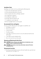
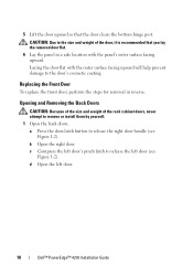
...) 8 Removing high-density rear door panels Recommended Tools and Supplies You may need the following tools and supplies to install the rack: • #2 Phillips screwdriver • Flat head screwdriver • 12-mm wrench • Needle-nose pliers • 4-mm Allen wrench (if you ... • Keys to the rack doors and side panels Removing and Replacing the Rack Doors CAUTION: Because of the size and weight of the rack cabinet doors, never attempt to release the door handle, then open the front door all the way (see Figure 1-1). 8 Dell™ PowerEdge™ 4210 Installation Guide CAUTION...
...) 8 Removing high-density rear door panels Recommended Tools and Supplies You may need the following tools and supplies to install the rack: • #2 Phillips screwdriver • Flat head screwdriver • 12-mm wrench • Needle-nose pliers • 4-mm Allen wrench (if you ... • Keys to the rack doors and side panels Removing and Replacing the Rack Doors CAUTION: Because of the size and weight of the rack cabinet doors, never attempt to release the door handle, then open the front door all the way (see Figure 1-1). 8 Dell™ PowerEdge™ 4210 Installation Guide CAUTION...

User Manual
Page 11
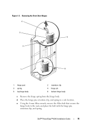
The hinge pin's retention clip prevents the hinge from the rack so that it clears the door's hinge-pin housing (see Figure 1-1). Removing the Front Door 1 2 3 4 1 door-latch button 3 hinge body 2 hinge pin 4 hinge-pin housing 3 While holding the door, pull the top hinge pin upward so that the door clears the hinge body. 4 Release the hinge pin. Figure 1-1. Dell™ PowerEdge™ 4210 Installation Guide 9 2 While holding the hinge pin out of the door's hinge-pin housing, pull the door slightly away from being pulled out of the hinge body.
The hinge pin's retention clip prevents the hinge from the rack so that it clears the door's hinge-pin housing (see Figure 1-1). Removing the Front Door 1 2 3 4 1 door-latch button 3 hinge body 2 hinge pin 4 hinge-pin housing 3 While holding the door, pull the top hinge pin upward so that the door clears the hinge body. 4 Release the hinge pin. Figure 1-1. Dell™ PowerEdge™ 4210 Installation Guide 9 2 While holding the hinge pin out of the door's hinge-pin housing, pull the door slightly away from being pulled out of the hinge body.
User Manual
Page 12
... help prevent damage to remove or install them by yourself. 1 Open the back doors. CAUTION: Due to release the left door. 10 Dell™ PowerEdge™ 4210 Installation Guide Laying the door flat with the panel's outer surface facing upward. d Open the left door (see Figure 1-2).... c Compress the left door's pinch latch to the size and weight of the rack cabinet doors, never attempt to the door's cosmetic coating. 5...
... help prevent damage to remove or install them by yourself. 1 Open the back doors. CAUTION: Due to release the left door. 10 Dell™ PowerEdge™ 4210 Installation Guide Laying the door flat with the panel's outer surface facing upward. d Open the left door (see Figure 1-2).... c Compress the left door's pinch latch to the size and weight of the rack cabinet doors, never attempt to the door's cosmetic coating. 5...

User Manual
Page 13
The hinge pins are designed to prevent them from the rack. a While supporting the door, pull the pin for the bottom hinge. Opening the Left Back Door 1 2 1 pinch latch 2 door-latch button 2 Remove the right door. b Repeat step a for the top hinge out of the door's hinge-pin housing (see Figure 1-3). Dell™ PowerEdge™ 4210 Installation Guide 11 You will hear a click as you pull the pin out of the hinge body. c Pull the door away from being pulled out of the door's hinge-pin housing. Figure 1-2.
The hinge pins are designed to prevent them from the rack. a While supporting the door, pull the pin for the bottom hinge. Opening the Left Back Door 1 2 1 pinch latch 2 door-latch button 2 Remove the right door. b Repeat step a for the top hinge out of the door's hinge-pin housing (see Figure 1-3). Dell™ PowerEdge™ 4210 Installation Guide 11 You will hear a click as you pull the pin out of the hinge body. c Pull the door away from being pulled out of the door's hinge-pin housing. Figure 1-2.

User Manual
Page 15
...panels in order to remove or install them by yourself. Removing a Side Panel 1 2 3 1 side panel (2) 3 handles (2) 2 locks (2) Dell™ PowerEdge™ 4210 Installation Guide 13 Also, although removing the side panels is not mandatory for removal in reverse. Figure 1-4. Removing the Side Panels CAUTION: ...of the panel (see Figure 1-4). Replacing the Back Doors To replace the back doors, perform the steps for installing systems in a rack, having the sides open makes it easier to install slide assemblies and support rails and to reverse the direction that the front door ...
...panels in order to remove or install them by yourself. Removing a Side Panel 1 2 3 1 side panel (2) 3 handles (2) 2 locks (2) Dell™ PowerEdge™ 4210 Installation Guide 13 Also, although removing the side panels is not mandatory for removal in reverse. Figure 1-4. Removing the Side Panels CAUTION: ...of the panel (see Figure 1-4). Replacing the Back Doors To replace the back doors, perform the steps for installing systems in a rack, having the sides open makes it easier to install slide assemblies and support rails and to reverse the direction that the front door ...

User Manual
Page 16
...complete the following steps: 1 Remove the front door. b Using the needle-nose pliers, remove the retention clip, and slide the hinge pin out of the rack cabinet side panels, never attempt to its cosmetic coating. 7 Repeat step 1 through step 6 for the other side panel. To reverse the direction that secures the.... 6 Place the panel in reverse. Reversing the Front Door (optional) NOTE: Use a 4-mm Allen wrench to remove the front-door hinge bodies from the rack. CAUTION: Because of the size and weight of the hinge body. 14 Dell™ PowerEdge™ 4210 Installation Guide
...complete the following steps: 1 Remove the front door. b Using the needle-nose pliers, remove the retention clip, and slide the hinge pin out of the rack cabinet side panels, never attempt to its cosmetic coating. 7 Repeat step 1 through step 6 for the other side panel. To reverse the direction that secures the.... 6 Place the panel in reverse. Reversing the Front Door (optional) NOTE: Use a 4-mm Allen wrench to remove the front-door hinge bodies from the rack. CAUTION: Because of the size and weight of the hinge body. 14 Dell™ PowerEdge™ 4210 Installation Guide
User Manual
Page 17
e Using the 4-mm Allen wrench, remove the Allen bolt that secures the hinge body to the rack, and place the bolt with the hinge pin, retention clip, and spring. Figure 1-5. d Place the hinge pin, retention clip, and spring in a safe location. Dell™ PowerEdge™ 4210 Installation Guide 15 Removing the Front-Door Hinges 4 3 5 2 1 6 1 hinge post 3 spring 5 top hinge body 2 retention clip 4 hinge pin 6 bottom hinge body c Remove the hinge spring from the hinge body.
e Using the 4-mm Allen wrench, remove the Allen bolt that secures the hinge body to the rack, and place the bolt with the hinge pin, retention clip, and spring. Figure 1-5. d Place the hinge pin, retention clip, and spring in a safe location. Dell™ PowerEdge™ 4210 Installation Guide 15 Removing the Front-Door Hinges 4 3 5 2 1 6 1 hinge post 3 spring 5 top hinge body 2 retention clip 4 hinge pin 6 bottom hinge body c Remove the hinge spring from the hinge body.

User Manual
Page 18
Reversing the Top and Bottom Hinges 1 2 3 4 5 7 1 hinge pin 3 spring 5 hinge post 7 front of the hinge body (see Figure 1-6). Figure 1-6. f Rotate the hinge body 180 degrees so that the hinge-pin holes are now on the right side of rack 6 2 top hinge body 4 retention clip 6 bottom hinge body 16 Dell™ PowerEdge™ 4210 Installation Guide
Reversing the Top and Bottom Hinges 1 2 3 4 5 7 1 hinge pin 3 spring 5 hinge post 7 front of the hinge body (see Figure 1-6). Figure 1-6. f Rotate the hinge body 180 degrees so that the hinge-pin holes are now on the right side of rack 6 2 top hinge body 4 retention clip 6 bottom hinge body 16 Dell™ PowerEdge™ 4210 Installation Guide

User Manual
Page 19
... use the Allen bolt to fasten the hinge body to the right side of the rack. 5 Rotate the front door 180 degrees so that secures the hinge body to the right side of the rack with the Allen bolt. i Slide the hinge pin into the hinge body. a Remove the Allen bolt that... bolt hole in the right side of the rack, and fasten the hinge body to the rack, and place the bolt in a safe location. b Rotate the hinge body 180 degrees so that the retention clip is below the spring. 4 Reverse the bottom hinge body. Dell™ PowerEdge™ 4210 Installation Guide 17 j Insert the...
... use the Allen bolt to fasten the hinge body to the right side of the rack. 5 Rotate the front door 180 degrees so that secures the hinge body to the right side of the rack with the Allen bolt. i Slide the hinge pin into the hinge body. a Remove the Allen bolt that... bolt hole in the right side of the rack, and fasten the hinge body to the rack, and place the bolt in a safe location. b Rotate the hinge body 180 degrees so that the retention clip is below the spring. 4 Reverse the bottom hinge body. Dell™ PowerEdge™ 4210 Installation Guide 17 j Insert the...

User Manual
Page 21
... then move your systems in any direction. Dell™ PowerEdge™ 4210 Installation Guide 19 CAUTION: Always level the rack and install the stabilizing feet before you install your systems. A fully loaded rack may cause the rack to align the rack in an upright, level position when the rack is situated on the front door. Proper contact...
... then move your systems in any direction. Dell™ PowerEdge™ 4210 Installation Guide 19 CAUTION: Always level the rack and install the stabilizing feet before you install your systems. A fully loaded rack may cause the rack to align the rack in an upright, level position when the rack is situated on the front door. Proper contact...

User Manual
Page 22
Figure 1-8. Adjusting the Leveling Feet 1 2 3 1 leveling foot stem 3 leveling pad 2 hex nut 20 Dell™ PowerEdge™ 4210 Installation Guide NOTE: If the rack is not leveled properly, you might not be able to install the stabilizer feet, which are necessary to prevent the rack from tipping over. 1 Using a screwdriver, lower the leveling foot until it rests on the floor. 2 If you need to lower the foot further, tighten the hex nut clockwise with a 12-mm wrench (see Figure 1-8). 3 Repeat steps 1 and 2 for the remaining leveling feet. 4 Ensure that the rack is level.
Figure 1-8. Adjusting the Leveling Feet 1 2 3 1 leveling foot stem 3 leveling pad 2 hex nut 20 Dell™ PowerEdge™ 4210 Installation Guide NOTE: If the rack is not leveled properly, you might not be able to install the stabilizer feet, which are necessary to prevent the rack from tipping over. 1 Using a screwdriver, lower the leveling foot until it rests on the floor. 2 If you need to lower the foot further, tighten the hex nut clockwise with a 12-mm wrench (see Figure 1-8). 3 Repeat steps 1 and 2 for the remaining leveling feet. 4 Ensure that the rack is level.
User Manual
Page 23
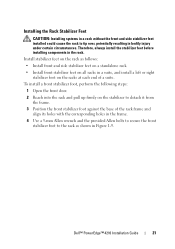
Dell™ PowerEdge™ 4210 Installation Guide 21 Therefore, always install the stabilizer feet before installing components in bodily injury under certain circumstances. Install stabilizer feet on the rack as shown in a suite, and install a left or right stabilizer foot on the stabilizer to tip over, potentially resulting in the rack. To install a front stabilizer...
Dell™ PowerEdge™ 4210 Installation Guide 21 Therefore, always install the stabilizer feet before installing components in bodily injury under certain circumstances. Install stabilizer feet on the rack as shown in a suite, and install a left or right stabilizer foot on the stabilizer to tip over, potentially resulting in the rack. To install a front stabilizer...
User Manual
Page 24
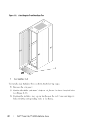
Attaching the Front Stabilizer Foot 1 1 front stabilizer foot To install a side stabilizer foot, perform the following steps: 1 Remove the side panel. 2 On the side of the rack frame's bottom rail, locate the three threaded holes (see Figure 1-10). 3 Position the stabilizer foot against the base of the rack frame and align its holes with the corresponding holes in the frame. 22 Dell™ PowerEdge™ 4210 Installation Guide Figure 1-9.
Attaching the Front Stabilizer Foot 1 1 front stabilizer foot To install a side stabilizer foot, perform the following steps: 1 Remove the side panel. 2 On the side of the rack frame's bottom rail, locate the three threaded holes (see Figure 1-10). 3 Position the stabilizer foot against the base of the rack frame and align its holes with the corresponding holes in the frame. 22 Dell™ PowerEdge™ 4210 Installation Guide Figure 1-9.
User Manual
Page 25
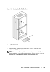
Dell™ PowerEdge™ 4210 Installation Guide 23 Attaching the Side Stabilizer Foot 1 1 lip of the rack mounting rails for information on the front and back of stabilizer foot 4 Use the 5-mm Allen wrench and the Allen bolts to secure the side stabilizer foot to the rack frame. NOTE: Unless you need to the white numbered labels on installing components in the rack. Refer to couple two or more racks, you may now install systems into the rack. Figure 1-10.
Dell™ PowerEdge™ 4210 Installation Guide 23 Attaching the Side Stabilizer Foot 1 1 lip of the rack mounting rails for information on the front and back of stabilizer foot 4 Use the 5-mm Allen wrench and the Allen bolts to secure the side stabilizer foot to the rack frame. NOTE: Unless you need to the white numbered labels on installing components in the rack. Refer to couple two or more racks, you may now install systems into the rack. Figure 1-10.
User Manual
Page 26
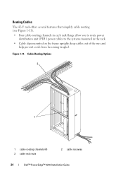
Cable-Routing Options 2 1 1 cable-routing channels (4) 3 cable exit route 2 cable raceway 24 Dell™ PowerEdge™ 4210 Installation Guide Figure 1-11. Routing Cables The 42-U rack offers several features that simplify cable routing (see Figure 1-11). • Four cable-routing channels in each rack flange allow you to route power distribution unit (PDU) power cables to the systems mounted in the rack. • Cable clips mounted on the frame uprights keep cables out of the way and help prevent cords from becoming tangled.
Cable-Routing Options 2 1 1 cable-routing channels (4) 3 cable exit route 2 cable raceway 24 Dell™ PowerEdge™ 4210 Installation Guide Figure 1-11. Routing Cables The 42-U rack offers several features that simplify cable routing (see Figure 1-11). • Four cable-routing channels in each rack flange allow you to route power distribution unit (PDU) power cables to the systems mounted in the rack. • Cable clips mounted on the frame uprights keep cables out of the way and help prevent cords from becoming tangled.

User Manual
Page 27
...(see Figure 1-11) NOTICE: To protect cables from Dell. Look for instance those that the plastic grommets are installed in the rack ceiling holes before routing cables to a cable raceway. Optional Door Kit With Removable Panels 1 1 captive screws Dell™ PowerEdge™ 4210 Installation Guide 25 Some systems may be ... by removing the door panels (see "Optional Door Kit With Removable Panels" on page 25) Figure 1-12. You can route cables out of the rack in two ways on a standard configuration: • Through the space at the top of the rear doors (see Figure 1-11) • Upward...
...(see Figure 1-11) NOTICE: To protect cables from Dell. Look for instance those that the plastic grommets are installed in the rack ceiling holes before routing cables to a cable raceway. Optional Door Kit With Removable Panels 1 1 captive screws Dell™ PowerEdge™ 4210 Installation Guide 25 Some systems may be ... by removing the door panels (see "Optional Door Kit With Removable Panels" on page 25) Figure 1-12. You can route cables out of the rack in two ways on a standard configuration: • Through the space at the top of the rear doors (see Figure 1-11) • Upward...
Best Practices Guide for Rack Enclosures
Page 4
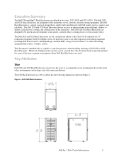
... following dimensions shown in two sizes, 24U (2420) and 42U (4220). Executive Summary The Dell™ PowerEdge™ Rack Enclosures are offered in Figure 1. The Dell Rack Enclosure is intended only as do other important networking equipment including Dell PowerVault™, Dell EqualLogic and Dell EMC storage, PowerConnect™ or other networking equipment like routers, switches, and etc.
... following dimensions shown in two sizes, 24U (2420) and 42U (4220). Executive Summary The Dell™ PowerEdge™ Rack Enclosures are offered in Figure 1. The Dell Rack Enclosure is intended only as do other important networking equipment including Dell PowerVault™, Dell EqualLogic and Dell EMC storage, PowerConnect™ or other networking equipment like routers, switches, and etc.


