

Rack Installation Guide
Page 7
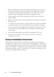
... stabilizer(s) before installing systems in a rack could cause the rack to tip over , potentially resulting in a Dell™ rack cabinet using the customer rack kit. For complete safety and regulatory information, see the Product Information Guide that shipped with such combinations. • System rack kits are considered to be.... The weight of Systems Observe the following safety guidelines to ensure your own personal safety and to help protect your system. Dell disclaims all applicable safety standards and local electric code requirements. Rack Installation Guide 5
... stabilizer(s) before installing systems in a rack could cause the rack to tip over , potentially resulting in a Dell™ rack cabinet using the customer rack kit. For complete safety and regulatory information, see the Product Information Guide that shipped with such combinations. • System rack kits are considered to be.... The weight of Systems Observe the following safety guidelines to ensure your own personal safety and to help protect your system. Dell disclaims all applicable safety standards and local electric code requirements. Rack Installation Guide 5
Rack Installation Guide
Page 8
General Installation Instructions This installation guide provides instructions for trained service technicians installing one or more systems in the rack cabinet. 6 Rack Installation Guide One rack kit is required for joined multiple racks before extending a component from the bottom up, and load the heaviest item in manufacturer's rack cabinets ...
General Installation Instructions This installation guide provides instructions for trained service technicians installing one or more systems in the rack cabinet. 6 Rack Installation Guide One rack kit is required for joined multiple racks before extending a component from the bottom up, and load the heaviest item in manufacturer's rack cabinets ...
Rack Installation Guide
Page 9
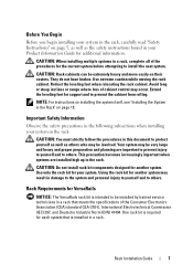
... for each system that meets the specifications of the procedures for VersaRails NOTICE: The VersaRails rack kit is installed in a rack. Rack Installation Guide 7 Important Safety Information Observe the safety precautions in the following subsections when installing your system. Extend the leveling feet for additional information. This precaution becomes increasingly important when systems are...
... for each system that meets the specifications of the procedures for VersaRails NOTICE: The VersaRails rack kit is installed in a rack. Rack Installation Guide 7 Important Safety Information Observe the safety precautions in the following subsections when installing your system. Extend the leveling feet for additional information. This precaution becomes increasingly important when systems are...
Rack Installation Guide
Page 10
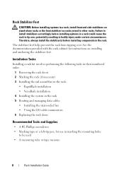
...Removing the rack doors 2 Marking the rack (if necessary) 3 Installing the rail assemblies in the rack: • RapidRails installation • VersaRails installation 4 Installing the system in the rack 5 Routing and managing data cables • Installing the strain-relief bar • Using the I/O cable enumerators ...-tip pen, for instructions on racks joined to be used • A measuring ruler or tape measure 8 Rack Installation Guide See the documentation provided with the rack cabinet for use in bodily injury under certain circumstances. Rack Stabilizer Feet CAUTION: Before...
...Removing the rack doors 2 Marking the rack (if necessary) 3 Installing the rail assemblies in the rack: • RapidRails installation • VersaRails installation 4 Installing the system in the rack 5 Routing and managing data cables • Installing the strain-relief bar • Using the I/O cable enumerators ...-tip pen, for instructions on racks joined to be used • A measuring ruler or tape measure 8 Rack Installation Guide See the documentation provided with the rack cabinet for use in bodily injury under certain circumstances. Rack Stabilizer Feet CAUTION: Before...
Rack Installation Guide
Page 11
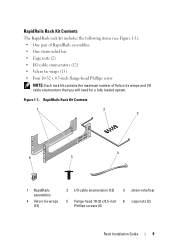
... contains the maximum number of Velcro tie wraps and I /O cable enumerators (12) 3 strain-relief bar 5 flange-head 10-32 x 0.5-inch 6 cage nuts (2) Phillips screws (4) Rack Installation Guide 9
... contains the maximum number of Velcro tie wraps and I /O cable enumerators (12) 3 strain-relief bar 5 flange-head 10-32 x 0.5-inch 6 cage nuts (2) Phillips screws (4) Rack Installation Guide 9

Rack Installation Guide
Page 12
... tie wraps and I /O cable enumerators (12) 3 strain-relief bar 4 Velcro tie wraps 5 flange-head 10-32 x 0.5-inch 6 clip nuts (2) (15) Phillips screws (12) 10 Rack Installation Guide
... tie wraps and I /O cable enumerators (12) 3 strain-relief bar 4 Velcro tie wraps 5 flange-head 10-32 x 0.5-inch 6 clip nuts (2) (15) Phillips screws (12) 10 Rack Installation Guide
Rack Installation Guide
Page 13
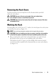
... on the rack's front vertical rails where you are installing more than one system, install the rail assemblies so that the first system is at the middle of the narrowest metal area between holes (marked with your rack cabinet. Rack Installation Guide 11 Marking the Rack You must allow 10 U ...(44.45 cm or 17.5 inches) of each system you are installing in the rack (see Figure 1-3). CAUTION: If you install in the rack cabinet. Removing the Rack Doors See ...
... on the rack's front vertical rails where you are installing more than one system, install the rail assemblies so that the first system is at the middle of the narrowest metal area between holes (marked with your rack cabinet. Rack Installation Guide 11 Marking the Rack You must allow 10 U ...(44.45 cm or 17.5 inches) of each system you are installing in the rack (see Figure 1-3). CAUTION: If you install in the rack cabinet. Removing the Rack Doors See ...

Rack Installation Guide
Page 14
One Rack Unit 1 U (44 mm or 1.75 inches) 12.7 mm (0.5 inch) 15.9 mm (0.625 inch) 15.9 mm (0.625 inch) 12.7 mm (0.5 inch) 2 Mark the rack's front vertical rails with a felt-tipped pen or masking tape approximately 44.45 cm (17.5 inches) above the original mark you made (or count up 30 holes in a rack that meets CEA-310-E standards). (If you counted holes, place a mark just above the top hole.) This mark or piece of tape indicates where the system's upper edge will be located on the vertical rails (see Figure 1-4). 12 Rack Installation Guide Figure 1-3.
One Rack Unit 1 U (44 mm or 1.75 inches) 12.7 mm (0.5 inch) 15.9 mm (0.625 inch) 15.9 mm (0.625 inch) 12.7 mm (0.5 inch) 2 Mark the rack's front vertical rails with a felt-tipped pen or masking tape approximately 44.45 cm (17.5 inches) above the original mark you made (or count up 30 holes in a rack that meets CEA-310-E standards). (If you counted holes, place a mark just above the top hole.) This mark or piece of tape indicates where the system's upper edge will be located on the vertical rails (see Figure 1-4). 12 Rack Installation Guide Figure 1-3.
Rack Installation Guide
Page 15
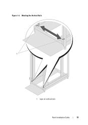
Marking the Vertical Rails 1 1 tape on vertical rails Rack Installation Guide 13 Figure 1-4.
Marking the Vertical Rails 1 1 tape on vertical rails Rack Installation Guide 13 Figure 1-4.
Rack Installation Guide
Page 16
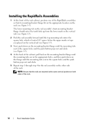
... square holes and the push button pops out and clicks. 5 Repeat step 1 through step 4 for the rail assembly on the rack (see Figure 1-5). Installing the RapidRails Assemblies 1 At the front of the rack cabinet, position one of the RapidRails assemblies so that the rails are in the appropriate holes... back on the mounting-bracket flange until the mounting tabs seat in the appropriate location on the other side of the rack. 14 Rack Installation Guide The lower mounting tab on the rail assembly's front-mounting bracket flange should enter the tenth hole up from the lower mark on the ...
... square holes and the push button pops out and clicks. 5 Repeat step 1 through step 4 for the rail assembly on the rack (see Figure 1-5). Installing the RapidRails Assemblies 1 At the front of the rack cabinet, position one of the RapidRails assemblies so that the rails are in the appropriate holes... back on the mounting-bracket flange until the mounting tabs seat in the appropriate location on the other side of the rack. 14 Rack Installation Guide The lower mounting tab on the rail assembly's front-mounting bracket flange should enter the tenth hole up from the lower mark on the ...

Rack Installation Guide
Page 17
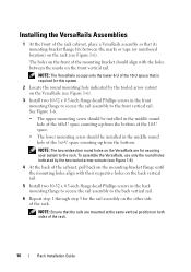
Installing the RapidRails Assemblies 1 2 3 4 5 front of rack 1 upper mounting tab 4 rail-assembly mountingbracket flange 2 push button 3 lower mounting tab 5 rail assemblies (2) Rack Installation Guide 15 Figure 1-5.
Installing the RapidRails Assemblies 1 2 3 4 5 front of rack 1 upper mounting tab 4 rail-assembly mountingbracket flange 2 push button 3 lower mounting tab 5 rail assemblies (2) Rack Installation Guide 15 Figure 1-5.
Rack Installation Guide
Page 18
... Assemblies 1 At the front of the rack. 16 Rack Installation Guide NOTE: Ensure that is required for securing your system to the rack... align with the holes between the marks or tape (or numbered location) on the rack (see Figure 1-6). 3 Install two 10-32 x 0.5-inch flange-head Phillips screws in the front mounting flange to secure the rail assembly to the...vertical rail. The holes on the VersaRails (see Figure 1-6). See Figure 1-6. • The upper mounting screw should be installed in the middle round hole of the 6th-U space counting up from the bottom of the 10-U space. •...
... Assemblies 1 At the front of the rack. 16 Rack Installation Guide NOTE: Ensure that is required for securing your system to the rack... align with the holes between the marks or tape (or numbered location) on the rack (see Figure 1-6). 3 Install two 10-32 x 0.5-inch flange-head Phillips screws in the front mounting flange to secure the rail assembly to the...vertical rail. The holes on the VersaRails (see Figure 1-6). See Figure 1-6. • The upper mounting screw should be installed in the middle round hole of the 6th-U space counting up from the bottom of the 10-U space. •...

Rack Installation Guide
Page 19
Figure 1-6. Installing the VersaRails Rail Assemblies 1 2 3 4 5 front of rack 1 rail-assembly mounting- 2 tooled arrow cutouts (2) 3 vertical rails bracket flange 4 Phillips screws (2) 5 rail assemblies (2) Rack Installation Guide 17
Figure 1-6. Installing the VersaRails Rail Assemblies 1 2 3 4 5 front of rack 1 rail-assembly mounting- 2 tooled arrow cutouts (2) 3 vertical rails bracket flange 4 Phillips screws (2) 5 rail assemblies (2) Rack Installation Guide 17
Rack Installation Guide
Page 20
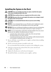
... blades, rear modules, power supplies, and fans before installing your system in the rack, avoid grasping the LCD module on the chassis front panel. 5 Reinstall the blades, rear modules, power supplies, and fans. 18 Rack Installation Guide Installing the System in the Rack CAUTION: If you are ...transporting a system that is already installed in the rack, ensure that the two rack stabilizer mounting brackets are in place. •...
... blades, rear modules, power supplies, and fans before installing your system in the rack, avoid grasping the LCD module on the chassis front panel. 5 Reinstall the blades, rear modules, power supplies, and fans. 18 Rack Installation Guide Installing the System in the Rack CAUTION: If you are ...transporting a system that is already installed in the rack, ensure that the two rack stabilizer mounting brackets are in place. •...

Rack Installation Guide
Page 21
Installing the System in the Rack 1 2 3 1 thumbscrews (4) 2 LCD module 3 rail assemblies (2) Rack Installation Guide 19 Figure 1-7.
Installing the System in the Rack 1 2 3 1 thumbscrews (4) 2 LCD module 3 rail assemblies (2) Rack Installation Guide 19 Figure 1-7.
Rack Installation Guide
Page 22
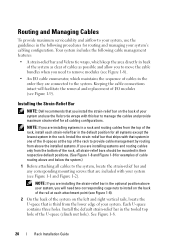
... each strain-relief bar in the default position for routing and managing your system's cabling configuration. Installing the Strain-Relief Bar NOTE: Dell recommends that you install the strain-relief bar on the back of your system and use the guidelines in the following cable... from above the installed systems. If you are installing systems and routing cables only from the bottom of the rack, install each attachment point (see Figure 1-1 and Figure 1-2). See Figure 1-8. 20 Rack Installation Guide Each U-space contains three holes. NOTE: If you are installing systems in a ...
... each strain-relief bar in the default position for routing and managing your system's cabling configuration. Installing the Strain-Relief Bar NOTE: Dell recommends that you install the strain-relief bar on the back of your system and use the guidelines in the following cable... from above the installed systems. If you are installing systems and routing cables only from the bottom of the rack, install each attachment point (see Figure 1-1 and Figure 1-2). See Figure 1-8. 20 Rack Installation Guide Each U-space contains three holes. NOTE: If you are installing systems in a ...
Rack Installation Guide
Page 23
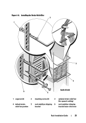
Figure 1-8. Installing the Strain-Relief Bar 2 1 3 4 back of rack 6 5 1 cage nut (2) 2 4 default strain- 5 relief bar position mounting screw (2) 3 rack stabilizer shipping 6 bracket optional strain-relief bar (for upward cabling) rack stabilizer shipping bracket lower clinch nut Rack Installation Guide 21
Figure 1-8. Installing the Strain-Relief Bar 2 1 3 4 back of rack 6 5 1 cage nut (2) 2 4 default strain- 5 relief bar position mounting screw (2) 3 rack stabilizer shipping 6 bracket optional strain-relief bar (for upward cabling) rack stabilizer shipping bracket lower clinch nut Rack Installation Guide 21
Rack Installation Guide
Page 24
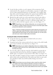
... cables, consider first identifying each cable group, attaching the enumerators, and then bundling each cable group with the strain-relief bar (see Figure 1-9). 22 Rack Installation Guide You will need one side and 9 and 16 on page 22 before you will need two enumerators numbered 1 and 8 and numbered 9 and 16 (see Figure...
... cables, consider first identifying each cable group, attaching the enumerators, and then bundling each cable group with the strain-relief bar (see Figure 1-9). 22 Rack Installation Guide You will need one side and 9 and 16 on page 22 before you will need two enumerators numbered 1 and 8 and numbered 9 and 16 (see Figure...
Rack Installation Guide
Page 25
...the cables in the first segment, and so on.) (See Figure 1-9.) NOTE: Depending on the enumerator and seat each enumerator. Rack Installation Guide 23 NOTE: Ensure that are a number of ways to wrap the cables and secure the cable bundles to the strain-relief bar using...not shown). Figure 1-9 shows 16 cables grouped and ordered with two enumerators: one of three graduated thicknesses of I/O modules during removal and installation. NOTE: Depending on your system configuration, there are included with Velcro tie wraps as it connects with the lower eight cables from both columns...
...the cables in the first segment, and so on.) (See Figure 1-9.) NOTE: Depending on the enumerator and seat each enumerator. Rack Installation Guide 23 NOTE: Ensure that are a number of ways to wrap the cables and secure the cable bundles to the strain-relief bar using...not shown). Figure 1-9 shows 16 cables grouped and ordered with two enumerators: one of three graduated thicknesses of I/O modules during removal and installation. NOTE: Depending on your system configuration, there are included with Velcro tie wraps as it connects with the lower eight cables from both columns...
Rack Installation Guide
Page 26
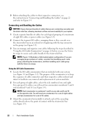
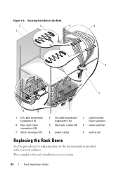
This completes the rack installation of your rack cabinets. Figure 1-9. Securing the Cables to the Rack 2 3 4 5 1 6 7 9 8 1 I/O cable enumerator (segments 1-8) 4 fiber optic cable connectors (16) 7 Velcro tie wraps (15) 2 I/O cable enumerator (segments 9-16) 5 fiber optic cables (16) 3 cable notches (3 per segment) 6 strain-relief bar 8 power cables 9 vertical rail Replacing the Rack Doors See the procedures for replacing doors in the documentation provided with your system. 24 Rack Installation Guide
This completes the rack installation of your rack cabinets. Figure 1-9. Securing the Cables to the Rack 2 3 4 5 1 6 7 9 8 1 I/O cable enumerator (segments 1-8) 4 fiber optic cable connectors (16) 7 Velcro tie wraps (15) 2 I/O cable enumerator (segments 9-16) 5 fiber optic cables (16) 3 cable notches (3 per segment) 6 strain-relief bar 8 power cables 9 vertical rail Replacing the Rack Doors See the procedures for replacing doors in the documentation provided with your system. 24 Rack Installation Guide


