EMC PowerEdge RAID Controller S140 Users Guide
Page 11
... only supported through the F2 key. inch SFF and PowerEdge NVMe PCIe SSD adapter, see the Lifecycle Controller User's Guide at dell.com/manuals. NOTE: Mixing NVMe PCIe SSDs and SATA drives is enabled for NVMe PCIe SSDs. Management applications for all supported RAID controllers and enclosures from a single graphical or command-line interface without using...
... only supported through the F2 key. inch SFF and PowerEdge NVMe PCIe SSD adapter, see the Lifecycle Controller User's Guide at dell.com/manuals. NOTE: Mixing NVMe PCIe SSDs and SATA drives is enabled for NVMe PCIe SSDs. Management applications for all supported RAID controllers and enclosures from a single graphical or command-line interface without using...
EMC PowerEdge RAID Controller S140 Users Guide
Page 12
...failure is not supported in UEFI HII; The following requirements must be met before hot-swapping a physical disk: • The system backplane or enclosure must support hot swapping for rebuilding. 12 Physical Disks This feature supports power management of the virtual disk. For example, you cannot mix an ...HDD and an NVMe PCIe SSD in the same virtual disk. NOTE: When hot-swapping a physical disk, ensure that the new disk is a power-saving feature ...
...failure is not supported in UEFI HII; The following requirements must be met before hot-swapping a physical disk: • The system backplane or enclosure must support hot swapping for rebuilding. 12 Physical Disks This feature supports power management of the virtual disk. For example, you cannot mix an ...HDD and an NVMe PCIe SSD in the same virtual disk. NOTE: When hot-swapping a physical disk, ensure that the new disk is a power-saving feature ...

EMC PowerEdge RAID Controller S140 Users Guide
Page 48
...console. Replace the physical disk. Perform a Rescan, to RAID and operating system installation is booted to locate a disk within an enclosure by deleting or initializing a virtual disk. b. Depending on the disk. Reinstall the physical disk and ensure that are not supported with...party driver installation for NVMe PCIe SSD failing Description: Solution While NVMe mode is seated correctly in RAID mode. 48 Troubleshooting your system is not working on PowerEdge R740 Description The Blink task allows you update the NVMe PCIe SSD firmware using Dell Update Package or ...
...console. Replace the physical disk. Perform a Rescan, to RAID and operating system installation is booted to locate a disk within an enclosure by deleting or initializing a virtual disk. b. Depending on the disk. Reinstall the physical disk and ensure that are not supported with...party driver installation for NVMe PCIe SSD failing Description: Solution While NVMe mode is seated correctly in RAID mode. 48 Troubleshooting your system is not working on PowerEdge R740 Description The Blink task allows you update the NVMe PCIe SSD firmware using Dell Update Package or ...

iDRAC9 with Lifecycle Controller Version 3.30.30.30 RACADM CLI Guide
Page 125
... rebuild: racadm storage cancelrebuild: racadm storage cancelbgi: • To generate and view information about the inventory of controllers, virtual disks, storage enclosures, and physical disk drives. • To generate and view information about the inventory of the inventory for storage root node. NOTE: If... you set the NVMe mode to the server. racadm storage get controllers RAID.Integrated.1-1 The following command is displayed as Unknown. To rebuild, cancel rebuild...
... rebuild: racadm storage cancelrebuild: racadm storage cancelbgi: • To generate and view information about the inventory of controllers, virtual disks, storage enclosures, and physical disk drives. • To generate and view information about the inventory of the inventory for storage root node. NOTE: If... you set the NVMe mode to the server. racadm storage get controllers RAID.Integrated.1-1 The following command is displayed as Unknown. To rebuild, cancel rebuild...
EMC Installation and Service Manual
Page 6
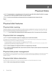
...PowerEdge C6400 enclosure supports the following configurations: 6 Dell EMC PowerEdge C6400 overview 1 Dell EMC PowerEdge C6400 overview The PowerEdge C6400 is an ultra-dense 2U enclosure that can support up to 12 x 3.5-inch SAS or SATA drives • diskless no backplane Topics: • Supported configurations • Front view of the Dell EMC PowerEdge C6400 enclosure... label Supported configurations The PowerEdge C6400 system supports the following drive configurations: • up to 24 x 2.5-inch SAS or SATA drives • up to 8 x 2.5-inch NVMe drives, with sleds •...
...PowerEdge C6400 enclosure supports the following configurations: 6 Dell EMC PowerEdge C6400 overview 1 Dell EMC PowerEdge C6400 overview The PowerEdge C6400 is an ultra-dense 2U enclosure that can support up to 12 x 3.5-inch SAS or SATA drives • diskless no backplane Topics: • Supported configurations • Front view of the Dell EMC PowerEdge C6400 enclosure... label Supported configurations The PowerEdge C6400 system supports the following drive configurations: • up to 24 x 2.5-inch SAS or SATA drives • up to 8 x 2.5-inch NVMe drives, with sleds •...
EMC Installation and Service Manual
Page 10
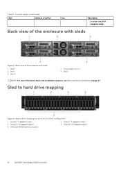
... to sled 4 10 Dell EMC PowerEdge C6400 overview Sled 1 5. Table 1. Sled 4 2. Drives 0-5 mapped to enter the BIOS progress mode. Control panel (continued) Item Indicator or button Icon Description to sled 1 3. Drives 12-17 mapped to sled 2 4. Drives 6-11 mapped to sled 3 5. (Optional) NVMe hard drive location 2. Sled 3 3. Back view of the enclosure with sleds 1. Sled...
... to sled 4 10 Dell EMC PowerEdge C6400 overview Sled 1 5. Table 1. Sled 4 2. Drives 0-5 mapped to enter the BIOS progress mode. Control panel (continued) Item Indicator or button Icon Description to sled 1 3. Drives 12-17 mapped to sled 2 4. Drives 6-11 mapped to sled 3 5. (Optional) NVMe hard drive location 2. Sled 3 3. Back view of the enclosure with sleds 1. Sled...
EMC Installation and Service Manual
Page 23
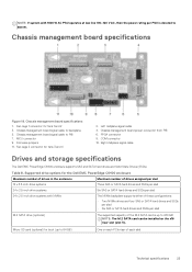
... specifications 23 Chassis management board signal cable to backplane 5. Micro-SD card (optional) for the Dell EMC PowerEdge C6400 enclosure Maximum number of drives in the enclosure Maximum number of drives assigned per sled 12 x 3.5-inch drive systems Three SAS or SATA hard...signal cable Drives and storage specifications The Dell EMC PowerEdge C6400 enclosure supports SAS and SATA hard drives and Solid State Drives (SSDs). Table 8. NOTE: If system with NVMe The NVMe backplane supports either of these configurations: • Two NVMe drives and four SAS or SATA hard ...
... specifications 23 Chassis management board signal cable to backplane 5. Micro-SD card (optional) for the Dell EMC PowerEdge C6400 enclosure Maximum number of drives in the enclosure Maximum number of drives assigned per sled 12 x 3.5-inch drive systems Three SAS or SATA hard...signal cable Drives and storage specifications The Dell EMC PowerEdge C6400 enclosure supports SAS and SATA hard drives and Solid State Drives (SSDs). Table 8. NOTE: If system with NVMe The NVMe backplane supports either of these configurations: • Two NVMe drives and four SAS or SATA hard ...

EMC Installation and Service Manual
Page 73
.... Backplane power connector 4. Signal cable to sled 4 4. NVMe ports 13 and 12 connect to sled 2 9. NVMe ports 7 and 6 connect to sled 3 6. NVMe ports 1 and 0 connect to maximize the hard drive space in hard drive backplane with NVMe: Figure 62. 24 x 2.5-in the hard drive bay.... sled 4 3. Backplane signal connector The image below shows the SAS Expander board: Installing and removing enclosure components 73 Connector for chassis management board cable 7. An expander board allows the C6400 to sled 1 SAS Expander board The SAS Expander board is integrated with the 24 x 2.5-in hard...
.... Backplane power connector 4. Signal cable to sled 4 4. NVMe ports 13 and 12 connect to sled 2 9. NVMe ports 7 and 6 connect to sled 3 6. NVMe ports 1 and 0 connect to maximize the hard drive space in hard drive backplane with NVMe: Figure 62. 24 x 2.5-in the hard drive bay.... sled 4 3. Backplane signal connector The image below shows the SAS Expander board: Installing and removing enclosure components 73 Connector for chassis management board cable 7. An expander board allows the C6400 to sled 1 SAS Expander board The SAS Expander board is integrated with the 24 x 2.5-in hard...

EMC Installation and Service Manual
Page 74
...expander connector 7. SAS expander C connector 9. Expander signal cable connector 2 2. SAS expander B connector 10. NVMe cable for sled 1(BP: BP_NVMe0 sled 1 to MB: left linking board) board) 74 Installing and removing enclosure components NVMe cable for sled 1(BP: sled 1 to MB: left linking board) 5. Power connector 3. SAS Expander... 4. Backplane signal cable 2(BP: BPSIG1 to MB: left linking 6. Figure 63. Cabling the 24 x 2.5-inch backplane with NVMe hard drives 1. SAS expander E connector 5. Expander signal cable connector 1 Backplane cable routing Figure 64.
...expander connector 7. SAS expander C connector 9. Expander signal cable connector 2 2. SAS expander B connector 10. NVMe cable for sled 1(BP: BP_NVMe0 sled 1 to MB: left linking board) board) 74 Installing and removing enclosure components NVMe cable for sled 1(BP: sled 1 to MB: left linking board) 5. Power connector 3. SAS Expander... 4. Backplane signal cable 2(BP: BPSIG1 to MB: left linking 6. Figure 63. Cabling the 24 x 2.5-inch backplane with NVMe hard drives 1. SAS expander E connector 5. Expander signal cable connector 1 Backplane cable routing Figure 64.

EMC Installation and Service Manual
Page 75
... sled 2 to Expander Board EXP_SAS B) 4. right linking board 16. 7. NVMe connector for sled 4 20. SATA cable for sled 3(BP: sled 3 to Expander Board EXP_SAS D) Installing and removing enclosure components 75 Right linking board 18. Linking board connector for sled 1 9. Backplane... signal cable 4(BP: BPSIG3 to MB: left linking board) 13. Linking board connector for sled 4 16. NVMe connector for sled 4 18. Expander SAS...
... sled 2 to Expander Board EXP_SAS B) 4. right linking board 16. 7. NVMe connector for sled 4 20. SATA cable for sled 3(BP: sled 3 to Expander Board EXP_SAS D) Installing and removing enclosure components 75 Right linking board 18. Linking board connector for sled 1 9. Backplane... signal cable 4(BP: BPSIG3 to MB: left linking board) 13. Linking board connector for sled 4 16. NVMe connector for sled 4 18. Expander SAS...

EMC Installation and Service Manual
Page 76
...Linking board connector for sled 3 13. Linking board connector for sled 1 5. Sled to drive mapping for sled 2 7. Linking board connector for the enclosure with 24 x 2.5-inch drives 1. SATA cable for sled 4(BP: SATA cable sled 4 to left linking board) 11. Signal cable sled 4(BP:... BP_SIG4 to right linking board) 15. Drives 6-11 mapped to sled 3 5. (Optional) NVMe hard drive location 2. SATA cable for sled 3(BP: SATA cable sled 3 to hard drive mapping Figure 67. Figure 66. Signal cable sled 3(BP: ...
...Linking board connector for sled 3 13. Linking board connector for sled 1 5. Sled to drive mapping for sled 2 7. Linking board connector for the enclosure with 24 x 2.5-inch drives 1. SATA cable for sled 4(BP: SATA cable sled 4 to left linking board) 11. Signal cable sled 4(BP:... BP_SIG4 to right linking board) 15. Drives 6-11 mapped to sled 3 5. (Optional) NVMe hard drive location 2. SATA cable for sled 3(BP: SATA cable sled 3 to hard drive mapping Figure 67. Figure 66. Signal cable sled 3(BP: ...

EMC Installation and Service Manual
Page 80
...x 2.5-inch drives with NVMe configuration. 1. Follow the procedure listed in Safety instructions. 2. You must route these cables properly when you remove them to the drives and backplane, you must remove the drives from the system. Install the drive cage into the enclosure. 3. NOTE: Observe ... NOTE: To prevent damage to prevent the cables from the backplane expander board. 80 Installing and removing enclosure components Follow the safety guidelines listed in Before working inside your enclosure. Figure 70. Follow the procedure listed in After working inside your...
...x 2.5-inch drives with NVMe configuration. 1. Follow the procedure listed in Safety instructions. 2. You must route these cables properly when you remove them to the drives and backplane, you must remove the drives from the system. Install the drive cage into the enclosure. 3. NOTE: Observe ... NOTE: To prevent damage to prevent the cables from the backplane expander board. 80 Installing and removing enclosure components Follow the safety guidelines listed in Before working inside your enclosure. Figure 70. Follow the procedure listed in After working inside your...

EMC Installation and Service Manual
Page 81
... the safety guidelines listed in Safety instructions. Install the backplane expander board into the enclosure, aligning the screw holes on the board with NVMe configuration. 1. Installing and removing enclosure components 81 Lift the backplane expander board out of the cable on the drive cage. 2. Figure 71. Using the Phillips #2 screwdriver, remove the screws...
... the safety guidelines listed in Safety instructions. Install the backplane expander board into the enclosure, aligning the screw holes on the board with NVMe configuration. 1. Installing and removing enclosure components 81 Lift the backplane expander board out of the cable on the drive cage. 2. Figure 71. Using the Phillips #2 screwdriver, remove the screws...
EMC Technical Specifications
Page 4
1 Dell EMC PowerEdge C6400 overview The PowerEdge C6400 is an ultra-dense 2U enclosure that can support up to four independent two-socket (2S) sleds. The PowerEdge C6400 enclosure supports the following drive configurations: • up to 24 x 2.5-inch SAS or SATA drives • up to 8 x 2.5-inch NVMe drives, with 16 x 2.5-inch SAS or SATA drives • up to 12 x 3.5-inch SAS or SATA drives • diskless no backplane 4 Dell EMC PowerEdge C6400 overview
1 Dell EMC PowerEdge C6400 overview The PowerEdge C6400 is an ultra-dense 2U enclosure that can support up to four independent two-socket (2S) sleds. The PowerEdge C6400 enclosure supports the following drive configurations: • up to 24 x 2.5-inch SAS or SATA drives • up to 8 x 2.5-inch NVMe drives, with 16 x 2.5-inch SAS or SATA drives • up to 12 x 3.5-inch SAS or SATA drives • diskless no backplane 4 Dell EMC PowerEdge C6400 overview
EMC Technical Specifications
Page 8
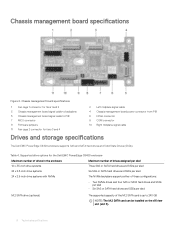
...management board signal cable to PIB 7 MCU connector 9 Firmware jumpers 11 Fan cage 2 connector for the Dell EMC PowerEdge C6400 enclosure Maximum number of drives in the enclosure 12 x 3.5-inch drive systems Maximum number of drives assigned per sled Three SAS or SATA hard drives ...and SSDs per sled 24 x 2.5-inch drive systems Six SAS or SATA hard drives and SSDs per sled 24 x 2.5-inch drive systems with NVMe The NVMe...
...management board signal cable to PIB 7 MCU connector 9 Firmware jumpers 11 Fan cage 2 connector for the Dell EMC PowerEdge C6400 enclosure Maximum number of drives in the enclosure 12 x 3.5-inch drive systems Maximum number of drives assigned per sled Three SAS or SATA hard drives ...and SSDs per sled 24 x 2.5-inch drive systems Six SAS or SATA hard drives and SSDs per sled 24 x 2.5-inch drive systems with NVMe The NVMe...


