
User Manual
Page 8
3 Press down on the release latch . 4 Pull the power supply unit out of the system . 5 Press the release latch down . 6 Pull the sled out of the system . 6 Installation and Configuration
3 Press down on the release latch . 4 Pull the power supply unit out of the system . 5 Press the release latch down . 6 Pull the sled out of the system . 6 Installation and Configuration

User Manual
Page 12
Connect a keyboard, mouse, or monitor (optional). 10 Installation and Configuration 4 Push the sled into the system until flush with the case and the release latch locks. Connecting the Keyboard, Mouse, and Monitor The connector on the front of your system has an icon indicating which cable to plug in.
Connect a keyboard, mouse, or monitor (optional). 10 Installation and Configuration 4 Push the sled into the system until flush with the case and the release latch locks. Connecting the Keyboard, Mouse, and Monitor The connector on the front of your system has an icon indicating which cable to plug in.

User Manual
Page 16
... max 55 A max 13 cm (5.1 in) 44.7 cm (17.6 in) 75 cm (29.5 in) 8-sled configuration: 42.4 kg (93.48 lbs.) 12-sled configuration: 48.13 kg (106.11 lbs.) 8-sled configuration: 27.4 kg (60.41 lbs.) 12-sled configuration: 32.02 kg (70.59 lbs.) Environmental NOTE: For additional information about environmental measurements...
... max 55 A max 13 cm (5.1 in) 44.7 cm (17.6 in) 75 cm (29.5 in) 8-sled configuration: 42.4 kg (93.48 lbs.) 12-sled configuration: 48.13 kg (106.11 lbs.) 8-sled configuration: 27.4 kg (60.41 lbs.) 12-sled configuration: 32.02 kg (70.59 lbs.) Environmental NOTE: For additional information about environmental measurements...

Hardware Owner's Manual
Page 3
Contents 1 About Your System 5 Front-Panel Features and Indicators 6 2 Using the System Setup Program 11 Start Menu 11 BIOS Setup Options at Boot 12 Console Redirection 12 Configuring Special Keys 13 General Help 14 Server Platform Setup Utility Screens 15 Main Menu 16 Advanced Menu 18 Server Management 33 Boot Menu 40 Security Menu 42 Save and Exit 43 POST Error Handling 45 3 Installing System Components 49 Recommended Tools 49 Inside the System 50 Sled Configuration 51 Sleds 52 3
Contents 1 About Your System 5 Front-Panel Features and Indicators 6 2 Using the System Setup Program 11 Start Menu 11 BIOS Setup Options at Boot 12 Console Redirection 12 Configuring Special Keys 13 General Help 14 Server Platform Setup Utility Screens 15 Main Menu 16 Advanced Menu 18 Server Management 33 Boot Menu 40 Security Menu 42 Save and Exit 43 POST Error Handling 45 3 Installing System Components 49 Recommended Tools 49 Inside the System 50 Sled Configuration 51 Sleds 52 3

Hardware Owner's Manual
Page 5
... are not supported. 1 About Your System The system includes the following configurations: • 8-sled system board + 3.5-inch hard-drive board + cables. • 8-sled system board + 2.5-inch hard-drive board + cables. • 8-sled system board + mezzanine card + 3.5-inch hard-drive board + cables. • 8-sled system board + mezzanine card + 2.5-inch hard-drive board + cables. • 12...
... are not supported. 1 About Your System The system includes the following configurations: • 8-sled system board + 3.5-inch hard-drive board + cables. • 8-sled system board + 2.5-inch hard-drive board + cables. • 8-sled system board + mezzanine card + 3.5-inch hard-drive board + cables. • 8-sled system board + mezzanine card + 2.5-inch hard-drive board + cables. • 12...

Hardware Owner's Manual
Page 6
... LAN connector 1 10/100/1 GB NIC LAN connector 2 On/Off button for sled Cover for the PowerEdge C5220 server, an eight sled SKU and a twelve sled SKU. There are two sled SKUs available for the Mezzanine card 6 About Your System Front-Panel Features and Indicators The Dell PowerEdge C5220 server is available in either a single-width or double-width...
... LAN connector 1 10/100/1 GB NIC LAN connector 2 On/Off button for sled Cover for the PowerEdge C5220 server, an eight sled SKU and a twelve sled SKU. There are two sled SKUs available for the Mezzanine card 6 About Your System Front-Panel Features and Indicators The Dell PowerEdge C5220 server is available in either a single-width or double-width...

Hardware Owner's Manual
Page 7
Figure 1-2. 12-Sled Front Features (Rotated Counterclockwise 90°) 2 1 3 2 1 Item Feature Description 1 VGA/USB connector VGA/USB 2.0 connector 2 NIC LAN ports 10/100/1G NIC LAN connector 1 10/100/1G NIC LAN connector 2 3 Power button On/Off button for sled About Your System 7
Figure 1-2. 12-Sled Front Features (Rotated Counterclockwise 90°) 2 1 3 2 1 Item Feature Description 1 VGA/USB connector VGA/USB 2.0 connector 2 NIC LAN ports 10/100/1G NIC LAN connector 1 10/100/1G NIC LAN connector 2 3 Power button On/Off button for sled About Your System 7

Hardware Owner's Manual
Page 8
Indicators Figure 1-3. 8-Sled Front View (Rotated Counterclockwise 90°) 4 32 1 20 31 7 65 Item Feature Status 1, 3 LAN link LED Off 2, 4 LAN activity LED Off LAN link LED Green ...
Indicators Figure 1-3. 8-Sled Front View (Rotated Counterclockwise 90°) 4 32 1 20 31 7 65 Item Feature Status 1, 3 LAN link LED Off 2, 4 LAN activity LED Off LAN link LED Green ...

Hardware Owner's Manual
Page 9
Item Feature 6 Identity LED 7 Power/Status Status Blue On Blue Off Blinking blue Green On Green Off Amber Off Blinking amber 12-Sled LEDs (Rotated Counterclockwise 90°) 4 32 1 Description Identifies the system Normal status Identifies the system with an interval System DC On System DC Off Normal status Event occurred in the system 20 31 7 65 About Your System 9
Item Feature 6 Identity LED 7 Power/Status Status Blue On Blue Off Blinking blue Green On Green Off Amber Off Blinking amber 12-Sled LEDs (Rotated Counterclockwise 90°) 4 32 1 Description Identifies the system Normal status Identifies the system with an interval System DC On System DC Off Normal status Event occurred in the system 20 31 7 65 About Your System 9

Hardware Owner's Manual
Page 50
Inside the System 8 7 6 5 1 PSU 1 3 PDB 1 5 power socket bracket 7 backplane 1 2 3 4 2 PSU 2 4 PDB 2 6 fan cage 8 sleds (12) 50 Installing System Components Read and follow the safety instructions that is not authorized is not covered by the online or telephone service and ...
Inside the System 8 7 6 5 1 PSU 1 3 PDB 1 5 power socket bracket 7 backplane 1 2 3 4 2 PSU 2 4 PDB 2 6 fan cage 8 sleds (12) 50 Installing System Components Read and follow the safety instructions that is not authorized is not covered by the online or telephone service and ...
Hardware Owner's Manual
Page 51
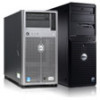
The following illustrations show the two server sled options and the sled numbering in your warranty. PowerEdge C5220 12-Sled SKU 1 2 3 4 5 6 7 8 9 10 11 12 Installing System Components 51 Sled Configuration CAUTION: Many repairs may also include an LSI 2008, 1GbE or 10GbE (post-RTS) mezzanine card. PowerEdge C5220 8-Sled SKU 12345678 NOTE: Sled SKU may only be done by your ... simple repairs as directed by the online or telephone service and support team. Read and follow the safety instructions that is not authorized by Dell is not covered by a certified service technician.
The following illustrations show the two server sled options and the sled numbering in your warranty. PowerEdge C5220 12-Sled SKU 1 2 3 4 5 6 7 8 9 10 11 12 Installing System Components 51 Sled Configuration CAUTION: Many repairs may also include an LSI 2008, 1GbE or 10GbE (post-RTS) mezzanine card. PowerEdge C5220 8-Sled SKU 12345678 NOTE: Sled SKU may only be done by your ... simple repairs as directed by the online or telephone service and support team. Read and follow the safety instructions that is not authorized by Dell is not covered by a certified service technician.

Hardware Owner's Manual
Page 52
... and follow the safety instructions that is not authorized by your product documentation, or as directed by a certified service technician. Sleds Removing a Sled CAUTION: Many repairs may only be immediately replaced with the product. You should be done by the online or telephone service ...and support team. Damage due to servicing that came with another sled or sled dummy. 1 Press the release latch down . 2 Pull the sled out of the system . 1 2 52 Installing System Components CAUTION: To ensure proper airflow in the ...
... and follow the safety instructions that is not authorized by your product documentation, or as directed by a certified service technician. Sleds Removing a Sled CAUTION: Many repairs may only be immediately replaced with the product. You should be done by the online or telephone service ...and support team. Damage due to servicing that came with another sled or sled dummy. 1 Press the release latch down . 2 Pull the sled out of the system . 1 2 52 Installing System Components CAUTION: To ensure proper airflow in the ...

Hardware Owner's Manual
Page 53
...: Many repairs may only be immediately replaced with another sled or sled dummy. You should only perform troubleshooting and simple repairs as authorized in the system, if a sled is not covered by a certified service technician. Push the sled into the system until flush with the product. Installing... System Components 53 Read and follow the safety instructions that is not authorized by Dell is removed it should be done by...
...: Many repairs may only be immediately replaced with another sled or sled dummy. You should only perform troubleshooting and simple repairs as authorized in the system, if a sled is not covered by a certified service technician. Push the sled into the system until flush with the product. Installing... System Components 53 Read and follow the safety instructions that is not authorized by Dell is removed it should be done by...

Hardware Owner's Manual
Page 54
... (x8, x4) (MHz) Component Total DIMM Slot Density Size A1 A2 A3 A4 8-Sled DDR3 ECC 1 1 UDIMM 1333 1R x8 2 Gb 2G • UDIMM/2048 MB*1 8-sled DDR3 ECC 1 2 UDIMM 1333 1R x8 2 Gb 4G • • UDIMM/2048 MB*2 8-sled DDR3 ECC 1 3 UDIMM 1333 1R x8 2 Gb 6G • ••... ECC 1 3 UDIMM 1333 2R/ x8 2 Gb 8G 2G 4G 2G UDIMM/4096 MB*1 1R +2048 MB*2 8-sled DDR3 ECC 1 3 UDIMM 1333 1R/ x8 2 Gb 10G 2G 4G 4G UDIMM/2048 MB*1 2R +4096 MB*2 8-sled DDR3 ECC 1 3 UDIMM 1333 2R x8 2 Gb 12G • • • UDIMM/4098 MB*3 54 Installing...
... (x8, x4) (MHz) Component Total DIMM Slot Density Size A1 A2 A3 A4 8-Sled DDR3 ECC 1 1 UDIMM 1333 1R x8 2 Gb 2G • UDIMM/2048 MB*1 8-sled DDR3 ECC 1 2 UDIMM 1333 1R x8 2 Gb 4G • • UDIMM/2048 MB*2 8-sled DDR3 ECC 1 3 UDIMM 1333 1R x8 2 Gb 6G • ••... ECC 1 3 UDIMM 1333 2R/ x8 2 Gb 8G 2G 4G 2G UDIMM/4096 MB*1 1R +2048 MB*2 8-sled DDR3 ECC 1 3 UDIMM 1333 1R/ x8 2 Gb 10G 2G 4G 4G UDIMM/2048 MB*1 2R +4096 MB*2 8-sled DDR3 ECC 1 3 UDIMM 1333 2R x8 2 Gb 12G • • • UDIMM/4098 MB*3 54 Installing...

Hardware Owner's Manual
Page 55
...- Memory Type/Size CPU DIMMs Type tion Memory Rank Type Speed (x8, x4) (MHz) 8-sled DDR3 ECC 1 4 UDIMM/2048 MB*4 8-sled DDR3 ECC 1 1 UDIMM/4096 MB*1 8-sled DDR3 ECC 1 2 UDIMM/4096 MB*2 8-sled DDR3 ECC 1 4 UDIMM/2048 MB*2 +4096 MB*2 8-sled DDR3 ECC 1 4 UDIMM/4096 MB*4 UDIMM 1333 1R x8 UDIMM 1333 2R x8 UDIMM...
...- Memory Type/Size CPU DIMMs Type tion Memory Rank Type Speed (x8, x4) (MHz) 8-sled DDR3 ECC 1 4 UDIMM/2048 MB*4 8-sled DDR3 ECC 1 1 UDIMM/4096 MB*1 8-sled DDR3 ECC 1 2 UDIMM/4096 MB*2 8-sled DDR3 ECC 1 4 UDIMM/2048 MB*2 +4096 MB*2 8-sled DDR3 ECC 1 4 UDIMM/4096 MB*4 UDIMM 1333 1R x8 UDIMM 1333 2R x8 UDIMM...

Hardware Owner's Manual
Page 56
... Rank Type Speed (x8, x4) (MHz) Component Total DIMM Slot Density Size A1 A2 A3 A4 12 sled DDR3 ECC 1 2 VLP 1333 2R x8 2Gb UDIMM/4096 MB*2 UDIMM 8G • • 12 sled DDR3 ECC 1 4 UDIMM/2048 MB*2+4096 MB*2 VLP 1333 UDIMM 2R x8 1Gb/2Gb 12G 2G 4G...16G Removing a Memory Module WARNING: The memory modules are hot to touch for the memory modules to servicing that came with the product. 1 Remove the sled from the system. 56 Installing System Components CAUTION: Many repairs may only be done by the online or telephone service and support team. You should...
... Rank Type Speed (x8, x4) (MHz) Component Total DIMM Slot Density Size A1 A2 A3 A4 12 sled DDR3 ECC 1 2 VLP 1333 2R x8 2Gb UDIMM/4096 MB*2 UDIMM 8G • • 12 sled DDR3 ECC 1 4 UDIMM/2048 MB*2+4096 MB*2 VLP 1333 UDIMM 2R x8 1Gb/2Gb 12G 2G 4G...16G Removing a Memory Module WARNING: The memory modules are hot to touch for the memory modules to servicing that came with the product. 1 Remove the sled from the system. 56 Installing System Components CAUTION: Many repairs may only be done by the online or telephone service and support team. You should...

Hardware Owner's Manual
Page 59
... Hard Drive CAUTION: Many repairs may only be done by the online or telephone service and support team. Top of sled 3 Remove the hard drive from the system. Bottom of sled Installing System Components 59 NOTE: Mixing SATA and SAS hard drive on page 51. 2 Select the hard drive to... servicing that came with the product. Read and follow the safety instructions that is not authorized by Dell is not supported. 1 Remove the sled from the sled docking bay. Damage due to replace and remove the four hard-drive bracket screws securing it underneath the...
... Hard Drive CAUTION: Many repairs may only be done by the online or telephone service and support team. Top of sled 3 Remove the hard drive from the system. Bottom of sled Installing System Components 59 NOTE: Mixing SATA and SAS hard drive on page 51. 2 Select the hard drive to... servicing that came with the product. Read and follow the safety instructions that is not authorized by Dell is not supported. 1 Remove the sled from the sled docking bay. Damage due to replace and remove the four hard-drive bracket screws securing it underneath the...

Hardware Owner's Manual
Page 61
Installing a 2.5-inch Hard Drive 1 Align the 2.5-inch hard-drive bracket on the new hard drive then replace the four screws. Installing System Components 61 NOTE: The correct orientation of the bracket with the arrow mark pointing towards the hard drive connector. 2 Connect the hard drive to the hard-drive board in the sled. 2.5" HDD 2.5" HDD 2.5" HDD 2.5" HDD HDD0 HDD1 HDD2 HDD3 3 Replace the sled hard-drive bracket screws underneath the sled.
Installing a 2.5-inch Hard Drive 1 Align the 2.5-inch hard-drive bracket on the new hard drive then replace the four screws. Installing System Components 61 NOTE: The correct orientation of the bracket with the arrow mark pointing towards the hard drive connector. 2 Connect the hard drive to the hard-drive board in the sled. 2.5" HDD 2.5" HDD 2.5" HDD 2.5" HDD HDD0 HDD1 HDD2 HDD3 3 Replace the sled hard-drive bracket screws underneath the sled.

Hardware Owner's Manual
Page 62
Read and follow the safety instructions that is not authorized by Dell is not supported. 1 Remove the sled from the system. Damage due to servicing that came with the product. See "Sled Configuration" on the 2.5 and 3.5-inch hard-drive board is not covered by your product documentation, or as directed by a certified service technician...
Read and follow the safety instructions that is not authorized by Dell is not supported. 1 Remove the sled from the system. Damage due to servicing that came with the product. See "Sled Configuration" on the 2.5 and 3.5-inch hard-drive board is not covered by your product documentation, or as directed by a certified service technician...

Hardware Owner's Manual
Page 63
2 Remove the hard-drive bracket screws from the cable clips. Top of sled 3.5" HDD HDD0 3.5" HDD HDD1 4 Disconnect the hard drive cables from the hard drive board and system board then lift the hard drive out of sled 3 Remove the hard drive cables from underneath the sled. Bottom of the sled . 2 3.5" HDD HDD0 HDD0 3.5" HDD HDD1 HDD1 1 HDD1 HDD0 SATA1 SATA0 Installing System Components 63
2 Remove the hard-drive bracket screws from the cable clips. Top of sled 3.5" HDD HDD0 3.5" HDD HDD1 4 Disconnect the hard drive cables from the hard drive board and system board then lift the hard drive out of sled 3 Remove the hard drive cables from underneath the sled. Bottom of the sled . 2 3.5" HDD HDD0 HDD0 3.5" HDD HDD1 HDD1 1 HDD1 HDD0 SATA1 SATA0 Installing System Components 63
