
Glossary
Page 8
.../Internet Protocol. termination - uplink port - USB - Symmetric multiprocessing. A standard interface that automatically supplies power to your system's hardware and customize the system's operation by setting features such as the last device at each processor has equal access to enable or disable the termination on these devices by an operating system, where...
.../Internet Protocol. termination - uplink port - USB - Symmetric multiprocessing. A standard interface that automatically supplies power to your system's hardware and customize the system's operation by setting features such as the last device at each processor has equal access to enable or disable the termination on these devices by an operating system, where...

User Manual
Page 14
... document or as a separate document. NOTE: Always check for SDHC) • Citrix XenServer 5.6 Feature Pack 1 NOTE: For the latest information on support.dell.com/manuals and read the updates first because they often supersede information in other documents. 12 Installation and...with the system. See Using the Baseboard Management Controller Guide at support.dell.com/manuals for information about system features, troubleshooting, and component replacement. See the Hardware Owner's Manual at support.dell.com/manuals. Supported Operating Systems • Microsoft Windows Server 2008 ...
... document or as a separate document. NOTE: Always check for SDHC) • Citrix XenServer 5.6 Feature Pack 1 NOTE: For the latest information on support.dell.com/manuals and read the updates first because they often supersede information in other documents. 12 Installation and...with the system. See Using the Baseboard Management Controller Guide at support.dell.com/manuals for information about system features, troubleshooting, and component replacement. See the Hardware Owner's Manual at support.dell.com/manuals. Supported Operating Systems • Microsoft Windows Server 2008 ...

Hardware Owner's Manual
Page 3
Contents 1 About Your System 5 Front-Panel Features and Indicators 6 2 Using the System Setup Program 11 Start Menu 11 BIOS Setup Options at Boot 12 Console Redirection 12 Configuring Special Keys 13 General Help 14 Server Platform Setup Utility Screens 15 Main Menu 16 Advanced Menu 18 Server Management 33 Boot Menu 40 Security Menu 42 Save and Exit 43 POST Error Handling 45 3 Installing System Components 49 Recommended Tools 49 Inside the System 50 Sled Configuration 51 Sleds 52 3
Contents 1 About Your System 5 Front-Panel Features and Indicators 6 2 Using the System Setup Program 11 Start Menu 11 BIOS Setup Options at Boot 12 Console Redirection 12 Configuring Special Keys 13 General Help 14 Server Platform Setup Utility Screens 15 Main Menu 16 Advanced Menu 18 Server Management 33 Boot Menu 40 Security Menu 42 Save and Exit 43 POST Error Handling 45 3 Installing System Components 49 Recommended Tools 49 Inside the System 50 Sled Configuration 51 Sleds 52 3

Hardware Owner's Manual
Page 6
...;) 4 2 1 3 2 1 Item Feature 1 VGA/USB connector 2 NIC LAN ports 3 Power button 4 Mezzanine card cover Description VGA/USB 2.0 connector 10/100/1 GB NIC LAN connector 1 10/100/1 GB NIC LAN connector 2 On/Off button for sled Cover for the PowerEdge C5220 server, an eight sled SKU and a ...twelve sled SKU. There are two sled SKUs available for the Mezzanine card 6 About Your System Front-Panel Features and Indicators The Dell PowerEdge C5220 server is available in either a single-width or double-width sled, each supporting either two 3.5-inch or four 2.5-inch hard ...
...;) 4 2 1 3 2 1 Item Feature 1 VGA/USB connector 2 NIC LAN ports 3 Power button 4 Mezzanine card cover Description VGA/USB 2.0 connector 10/100/1 GB NIC LAN connector 1 10/100/1 GB NIC LAN connector 2 On/Off button for sled Cover for the PowerEdge C5220 server, an eight sled SKU and a ...twelve sled SKU. There are two sled SKUs available for the Mezzanine card 6 About Your System Front-Panel Features and Indicators The Dell PowerEdge C5220 server is available in either a single-width or double-width sled, each supporting either two 3.5-inch or four 2.5-inch hard ...

Hardware Owner's Manual
Page 7
Figure 1-2. 12-Sled Front Features (Rotated Counterclockwise 90°) 2 1 3 2 1 Item Feature Description 1 VGA/USB connector VGA/USB 2.0 connector 2 NIC LAN ports 10/100/1G NIC LAN connector 1 10/100/1G NIC LAN connector 2 3 Power button On/Off button for sled About Your System 7
Figure 1-2. 12-Sled Front Features (Rotated Counterclockwise 90°) 2 1 3 2 1 Item Feature Description 1 VGA/USB connector VGA/USB 2.0 connector 2 NIC LAN ports 10/100/1G NIC LAN connector 1 10/100/1G NIC LAN connector 2 3 Power button On/Off button for sled About Your System 7

Hardware Owner's Manual
Page 8
Indicators Figure 1-3. 8-Sled Front View (Rotated Counterclockwise 90°) 4 32 1 20 31 7 65 Item Feature Status 1, 3 LAN link LED Off 2, 4 LAN activity LED Off LAN link LED Green LAN activity LED Off LAN link LED Green LAN activity LED Off ...
Indicators Figure 1-3. 8-Sled Front View (Rotated Counterclockwise 90°) 4 32 1 20 31 7 65 Item Feature Status 1, 3 LAN link LED Off 2, 4 LAN activity LED Off LAN link LED Green LAN activity LED Off LAN link LED Green LAN activity LED Off ...

Hardware Owner's Manual
Page 9
Item Feature 6 Identity LED 7 Power/Status Status Blue On Blue Off Blinking blue Green On Green Off Amber Off Blinking amber 12-Sled LEDs (Rotated Counterclockwise 90°) 4 32 1 Description Identifies the system Normal status Identifies the system with an interval System DC On System DC Off Normal status Event occurred in the system 20 31 7 65 About Your System 9
Item Feature 6 Identity LED 7 Power/Status Status Blue On Blue Off Blinking blue Green On Green Off Amber Off Blinking amber 12-Sled LEDs (Rotated Counterclockwise 90°) 4 32 1 Description Identifies the system Normal status Identifies the system with an interval System DC On System DC Off Normal status Event occurred in the system 20 31 7 65 About Your System 9

Hardware Owner's Manual
Page 10
Item Feature Status 1, 3 LAN link LED Off 2, 4 LAN activity LED Off LAN link LED Green LAN activity LED Off LAN link LED Green LAN activity LED Off ...
Item Feature Status 1, 3 LAN link LED Off 2, 4 LAN activity LED Off LAN link LED Green LAN activity LED Off LAN link LED Green LAN activity LED Off ...

Hardware Owner's Manual
Page 11
... communication ports to prevent any conflicts • When changing the password or making other changes to execute from unauthorized use • Protocol and feature enabling/disabling • Power Management features This Setup utility should be executed under the following conditions: • When changing the system configuration • When a configuration error is stored...
... communication ports to prevent any conflicts • When changing the password or making other changes to execute from unauthorized use • Protocol and feature enabling/disabling • Power Management features This Setup utility should be executed under the following conditions: • When changing the system configuration • When a configuration error is stored...

Hardware Owner's Manual
Page 23
Using the System Setup Program 23 Memory Configuration Menu Fields Settings Advanced\Memory Configuration Memory Frequency Auto* 1066 MHz 1333 MHz Memory Remapping (3 GB - 4 GB) Disable* Enable Comments Auto-Detect the memory running speed or set running speed up to the space above 4 GB with this feature disabled/enabled. Memory remapping relocates memory space 3 GB~4 GB to 1066/1333 MHz.
Using the System Setup Program 23 Memory Configuration Menu Fields Settings Advanced\Memory Configuration Memory Frequency Auto* 1066 MHz 1333 MHz Memory Remapping (3 GB - 4 GB) Disable* Enable Comments Auto-Detect the memory running speed or set running speed up to the space above 4 GB with this feature disabled/enabled. Memory remapping relocates memory space 3 GB~4 GB to 1066/1333 MHz.

Hardware Owner's Manual
Page 25
...entering setup, BIOS auto detects the presence of SATA devices and displays the status of detected SATA hard drives. Disable/Enable the feature that allows SATA hard drives to initiate link power management transitions. Menu Fields SATA Port1/SSI Hard drive 1 Settings SATA Port2/Hard... drive 0 SATA Port3/Hard drive 1 SATA Port4/Hard drive 2 SATA Port5/Hard drive 3 Power Saving Features Disable Enable* Hard drive Security Erase Disable* Enable Comments While entering setup, BIOS auto detects the presence of SATA devices and displays the status ...
...entering setup, BIOS auto detects the presence of SATA devices and displays the status of detected SATA hard drives. Disable/Enable the feature that allows SATA hard drives to initiate link power management transitions. Menu Fields SATA Port1/SSI Hard drive 1 Settings SATA Port2/Hard... drive 0 SATA Port3/Hard drive 1 SATA Port4/Hard drive 2 SATA Port5/Hard drive 3 Power Saving Features Disable Enable* Hard drive Security Erase Disable* Enable Comments While entering setup, BIOS auto detects the presence of SATA devices and displays the status ...
Hardware Owner's Manual
Page 28
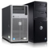
To enable this feature, an add-on NIC with SR-IOV support is required. Auto detects the PCIe maximum payload size or sets it to 128/256 Bytes. Menu Fields SR-IOV Global Enable Settings Disable* Enable Maximum Payload Size WHEA Support Auto* 128 Bytes 256 Bytes Disable* Enable Comments Disable/Enable BIOS support for SR-IOV devices. Enable or disable Windows Hardware Error Architecture (WHEA) 28 Using the System Setup Program
To enable this feature, an add-on NIC with SR-IOV support is required. Auto detects the PCIe maximum payload size or sets it to 128/256 Bytes. Menu Fields SR-IOV Global Enable Settings Disable* Enable Maximum Payload Size WHEA Support Auto* 128 Bytes 256 Bytes Disable* Enable Comments Disable/Enable BIOS support for SR-IOV devices. Enable or disable Windows Hardware Error Architecture (WHEA) 28 Using the System Setup Program

Using the Baseboard Management Controller
Page 3
... Functions 5 Using the Web UI 5 Logging in to the Web User Interface 6 System Features 8 System Information 8 Component Information 9 Server Identify 10 Firmware Update 11 Front Panel User Interface 13 Power Button 13 LEDs 13 System Information 16 System Information ...
... Functions 5 Using the Web UI 5 Logging in to the Web User Interface 6 System Features 8 System Information 8 Component Information 9 Server Identify 10 Firmware Update 11 Front Panel User Interface 13 Power Button 13 LEDs 13 System Information 16 System Information ...
Using the Baseboard Management Controller
Page 5
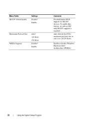
Supported Platform PowerEdge C5220 BMC Key Features and Functions The following lists the supported features of the BMC: • Support for IPMI v1.5 and v2.0 • Out-of-band monitoring and control for server management over LAN • Dedicated NIC...virtual media. Introduction This section introduces the Baseboard Management Controller (BMC) and includes the requirements for LAN channel Using the Web UI The BMC firmware features an embedded web server, enabling users to connect to the BMC using an Internet browser (Microsoft Internet Explorer) without needing to install KVM and virtual...
Supported Platform PowerEdge C5220 BMC Key Features and Functions The following lists the supported features of the BMC: • Support for IPMI v1.5 and v2.0 • Out-of-band monitoring and control for server management over LAN • Dedicated NIC...virtual media. Introduction This section introduces the Baseboard Management Controller (BMC) and includes the requirements for LAN channel Using the Web UI The BMC firmware features an embedded web server, enabling users to connect to the BMC using an Internet browser (Microsoft Internet Explorer) without needing to install KVM and virtual...

Using the Baseboard Management Controller
Page 8
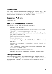
...BIOS version for the system. MB Position Displays the current position of the system. Table 1-2. Chassis Type Displays the chassis type. System Features System Information The System Information page enables you to view the Remote Management Controller. Chassis Version Displays the chassis version number. BMC Summary ... YYYY HH:MM:SS BMC Date & Time Current date and time in the form: W, DD M YYYY HH:MM:SS BMC Chipset Dell Remote Management Controller type. Click System Information to view the BMC firmware version, BIOS version, and Chassis version. Firmware Revision...
...BIOS version for the system. MB Position Displays the current position of the system. Table 1-2. Chassis Type Displays the chassis type. System Features System Information The System Information page enables you to view the Remote Management Controller. Chassis Version Displays the chassis version number. BMC Summary ... YYYY HH:MM:SS BMC Date & Time Current date and time in the form: W, DD M YYYY HH:MM:SS BMC Chipset Dell Remote Management Controller type. Click System Information to view the BMC firmware version, BIOS version, and Chassis version. Firmware Revision...
Using the Baseboard Management Controller
Page 11
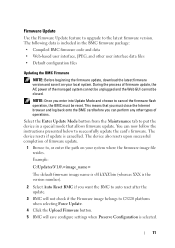
NOTE: Once you want the BMC to auto reset after the update. 3 BMC will not check if the Firmware image belongs to C5220 platform when selecting Force Update. 4 Click the Upload Firmware button. 5 BMC will save it on your local system. During the process of firmware update, the ... and the Web GUI cannot be reset. This means that allows firmware update. The following data is selected. 11 Firmware Update Use the Firmware Update feature to upgrade to , or enter the path on your system where the firmware image file resides. The device resets if update is cancelled.
NOTE: Once you want the BMC to auto reset after the update. 3 BMC will not check if the Firmware image belongs to C5220 platform when selecting Force Update. 4 Click the Upload Firmware button. 5 BMC will save it on your local system. During the process of firmware update, the ... and the Web GUI cannot be reset. This means that allows firmware update. The following data is selected. 11 Firmware Update Use the Firmware Update feature to upgrade to , or enter the path on your system where the firmware image file resides. The device resets if update is cancelled.

Using the Baseboard Management Controller
Page 28
... user has to press to unlock and stop mouse redirection. When the single cursor checkbox is selected, only the redirect mouse cursor is an added feature for IPMI. Here is absolute coordinates or relative 28 Select this option to select mouse mode to make the settings active. Mouse Mode Item Current...
... user has to press to unlock and stop mouse redirection. When the single cursor checkbox is selected, only the redirect mouse cursor is an added feature for IPMI. Here is absolute coordinates or relative 28 Select this option to select mouse mode to make the settings active. Mouse Mode Item Current...

Using the Baseboard Management Controller
Page 45
... at least 1024 x 768 pixels at 60 Hz with 32 bit color. Console Redirection The Console Redirection page enables you to use the Console Redirection feature, your browser must have the JRE installed in full screen mode if your operating system. You cannot view the console in your monitor resolution is...
... at least 1024 x 768 pixels at 60 Hz with 32 bit color. Console Redirection The Console Redirection page enables you to use the Console Redirection feature, your browser must have the JRE installed in full screen mode if your operating system. You cannot view the console in your monitor resolution is...