Service Manual
Page 9
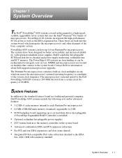
... memory (standard), upgradable to 2 GB • SCSI backplane board supporting up to four Pentium Pro microprocessors. Contact Dell for the Dell PowerEdge 6100/200 system is 200 MHz derived from a system clock frequency of the system clock frequency. The Pentium Pro microprocessor contains a built-in... frequency to a multiple of 66 MHz. System Features In addition to the standard features found in a traditional personal computer, Dell PowerEdge 6100 systems include the following new and/or advanced features: • 512 KB of cache memory internal to each Pentium Pro microprocessor...
... memory (standard), upgradable to 2 GB • SCSI backplane board supporting up to four Pentium Pro microprocessors. Contact Dell for the Dell PowerEdge 6100/200 system is 200 MHz derived from a system clock frequency of the system clock frequency. The Pentium Pro microprocessor contains a built-in... frequency to a multiple of 66 MHz. System Features In addition to the standard features found in a traditional personal computer, Dell PowerEdge 6100 systems include the following new and/or advanced features: • 512 KB of cache memory internal to each Pentium Pro microprocessor...

Service Manual
Page 10
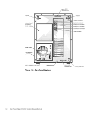
back of computer left side right side front of system features, see the "Dell PowerEdge 4100 and 6100 Systems Rack Kit Installation Guide" (P/N 40722). For information about installing the PowerEdge 6100 systems in upgradable flash memory attached to the EISA bus • Integrated super I/O...; Recessed power and reset buttons to prevent accidental system interruptions All of these features are briefly described in Figure 1-1. 1-2 Dell PowerEdge 6100/200 System Service Manual • BIOS in a rack, see "Technical Specifications" found later in this chapter. ages and temperatures...
back of computer left side right side front of system features, see the "Dell PowerEdge 4100 and 6100 Systems Rack Kit Installation Guide" (P/N 40722). For information about installing the PowerEdge 6100 systems in upgradable flash memory attached to the EISA bus • Integrated super I/O...; Recessed power and reset buttons to prevent accidental system interruptions All of these features are briefly described in Figure 1-1. 1-2 Dell PowerEdge 6100/200 System Service Manual • BIOS in a rack, see "Technical Specifications" found later in this chapter. ages and temperatures...

Service Manual
Page 12
memory module secondary microprocessor module or terminator module primary microprocessor module expansion slot (10) support panel system board Figure 1-3. Front/Left Internal View external drive bay (4) control panel internal drive bay (6) hard-disk drive security lock air intake panel (cooling fans are located behind the air intake panel) 1-4 Dell PowerEdge 6100/200 System Service Manual
memory module secondary microprocessor module or terminator module primary microprocessor module expansion slot (10) support panel system board Figure 1-3. Front/Left Internal View external drive bay (4) control panel internal drive bay (6) hard-disk drive security lock air intake panel (cooling fans are located behind the air intake panel) 1-4 Dell PowerEdge 6100/200 System Service Manual
Service Manual
Page 14
Back Panel Features lower SCSI connector slot security cable slot 1-6 Dell PowerEdge 6100/200 System Service Manual keylock closeout panel or optional power supply upper SCSI connector slot keylock mouse connector keyboard connector serial port 2 connector serial port 1 connector parallel port connector video connector power supply fault indicator (red LED) online indicator (green LED) SMB connector Figure 1-5.
Back Panel Features lower SCSI connector slot security cable slot 1-6 Dell PowerEdge 6100/200 System Service Manual keylock closeout panel or optional power supply upper SCSI connector slot keylock mouse connector keyboard connector serial port 2 connector serial port 1 connector parallel port connector video connector power supply fault indicator (red LED) online indicator (green LED) SMB connector Figure 1-5.

Service Manual
Page 15
...cards the next time the system is 64 MB of eight SIMMS. SIMMs in different banks may differ in the Dell PowerEdge 6100/200 System Installation and Troubleshooting Guide. Memory Module and SIMM Sockets For more detailed information about SIMM installation guidelines and samples ...GB). J16 bank 2 J12 bank 2 bank 1 bank 1 J5 J1 Figure 1-6. Chapter 5, "Using the System Configuration Utility," in the Dell PowerEdge 6100/200 System User's Guide describes the system configuration utility and provides instructions for information on the memory module (see "Adding Memory" in Chapter 8, ...
...cards the next time the system is 64 MB of eight SIMMS. SIMMs in different banks may differ in the Dell PowerEdge 6100/200 System Installation and Troubleshooting Guide. Memory Module and SIMM Sockets For more detailed information about SIMM installation guidelines and samples ...GB). J16 bank 2 J12 bank 2 bank 1 bank 1 J5 J1 Figure 1-6. Chapter 5, "Using the System Configuration Utility," in the Dell PowerEdge 6100/200 System User's Guide describes the system configuration utility and provides instructions for information on the memory module (see "Adding Memory" in Chapter 8, ...

Service Manual
Page 16
... consists of the system cooling fans. The expansion-card connectors are normally used in conjunction with 256 colors. For 1-8 Dell PowerEdge 6100/200 System Service Manual to the EISA local bus. In the standard Dell PowerEdge 6100 system configuration, one Ultra/Wide SCSI host adapter on the system board. The ten expansion-card slots consist of DRAM...
... consists of the system cooling fans. The expansion-card connectors are normally used in conjunction with 256 colors. For 1-8 Dell PowerEdge 6100/200 System Service Manual to the EISA local bus. In the standard Dell PowerEdge 6100 system configuration, one Ultra/Wide SCSI host adapter on the system board. The ten expansion-card slots consist of DRAM...
Service Manual
Page 18
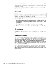
...When the fault indicator (red LED) on the power supply is configured as the last device on the system board or drives. 1-10 Dell PowerEdge 6100/200 System Service Manual Therefore, when you use only SCSI cables purchased from the other five con- Therefore, any additional devices attached to their terminators... supply provides the DC operating voltages and currents listed in to 265 VAC at 50 or 60 Hz. See the documentation provided with the Dell PowerEdge 6100 systems. The 50-pin SCSI cable has six connectors: • The connector at the end of 90 to the connector via an adapter...
...When the fault indicator (red LED) on the power supply is configured as the last device on the system board or drives. 1-10 Dell PowerEdge 6100/200 System Service Manual Therefore, when you use only SCSI cables purchased from the other five con- Therefore, any additional devices attached to their terminators... supply provides the DC operating voltages and currents listed in to 265 VAC at 50 or 60 Hz. See the documentation provided with the Dell PowerEdge 6100 systems. The 50-pin SCSI cable has six connectors: • The connector at the end of 90 to the connector via an adapter...

Service Manual
Page 20
... (black) common (black) +5 VDC (red) +5 VDC (red) common (black) common (black) +5 VDC (red) +5 VDC (red) common (black) Figure 1-9. DC Power Connector PWR2 and PWR3 1-12 Dell PowerEdge 6100/200 System Service Manual Pin 7 on the system board connector is not used. NC_3INH common (black) POWER_GOOD (gray) common (black) +5 VFP (violet) +3.3 VDC sense (orange) -3.3 VDC...
... (black) common (black) +5 VDC (red) +5 VDC (red) common (black) common (black) +5 VDC (red) +5 VDC (red) common (black) Figure 1-9. DC Power Connector PWR2 and PWR3 1-12 Dell PowerEdge 6100/200 System Service Manual Pin 7 on the system board connector is not used. NC_3INH common (black) POWER_GOOD (gray) common (black) +5 VFP (violet) +3.3 VDC sense (orange) -3.3 VDC...
Service Manual
Page 22
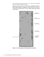
... (PWRFD) system board connector (PWR2) diagnostics port (J32) system board connector (PWR3) SCSI backplane board connector (PWRSCSI) Figure 1-12. Power-Supply Paralleling Board Connectors 1-14 Dell PowerEdge 6100/200 System Service Manual
... (PWRFD) system board connector (PWR2) diagnostics port (J32) system board connector (PWR3) SCSI backplane board connector (PWRSCSI) Figure 1-12. Power-Supply Paralleling Board Connectors 1-14 Dell PowerEdge 6100/200 System Service Manual

Service Manual
Page 24
... not supported/not used • IDE • J8G1 • HD LED 1 • J5E1 • J4G1 • I2C • HD LED 2 • J2A3 • C5B1 1-16 Dell PowerEdge 6100/200 System Service Manual System Board Layout The subsections that follow provide service-related information about the system board components.
... not supported/not used • IDE • J8G1 • HD LED 1 • J5E1 • J4G1 • I2C • HD LED 2 • J2A3 • C5B1 1-16 Dell PowerEdge 6100/200 System Service Manual System Board Layout The subsections that follow provide service-related information about the system board components.

Service Manual
Page 26
... the RTC are retained during reset. BIOS WRITE FLOPPY 0 (default) Enables BIOS update of flash memory. (Dell default) Enables 1.44-MB diskette drive size or autodetection. Enables forced 2.88-MB diskette drive size detection. 1-18 Dell PowerEdge 6100/200 System Service Manual Disables BIOS update of flash memory. RESERVED (default) Reserved (do not change ). Enables...
... the RTC are retained during reset. BIOS WRITE FLOPPY 0 (default) Enables BIOS update of flash memory. (Dell default) Enables 1.44-MB diskette drive size or autodetection. Enables forced 2.88-MB diskette drive size detection. 1-18 Dell PowerEdge 6100/200 System Service Manual Disables BIOS update of flash memory. RESERVED (default) Reserved (do not change ). Enables...

Service Manual
Page 29
... (POWER) 6 SCA-2 compatible SCSI connectors (SLOTnID=n, on other side) server-management bus connector (SERVER MANAGEMENT) control (front) panel connector (CONTROL PANEL) Figure 1-17. J105 (default) 200/66 MHz microprocessor installed. J106 (default) Microprocessor is installed in adjacent slot. Table 1-3. Do not change. SCSI Backplane Board System Overview 1-21 Microprocessor is not...
... (POWER) 6 SCA-2 compatible SCSI connectors (SLOTnID=n, on other side) server-management bus connector (SERVER MANAGEMENT) control (front) panel connector (CONTROL PANEL) Figure 1-17. J105 (default) 200/66 MHz microprocessor installed. J106 (default) Microprocessor is installed in adjacent slot. Table 1-3. Do not change. SCSI Backplane Board System Overview 1-21 Microprocessor is not...

Service Manual
Page 30
... IRQ13 Used by the math coprocessor to indicate coprocessor error IRQ14 Available for use by expansion card IRQ15 Available for use by expansion card 1-22 Dell PowerEdge 6100/200 System Service Manual SCSI Backplane Board Connectors Connector Description CONTROL PANEL Control panel connector POWER Power input connector SCSI Ultra/Wide SCSI cable connector SERVER...
... IRQ13 Used by the math coprocessor to indicate coprocessor error IRQ14 Available for use by expansion card IRQ15 Available for use by expansion card 1-22 Dell PowerEdge 6100/200 System Service Manual SCSI Backplane Board Connectors Connector Description CONTROL PANEL Control panel connector POWER Power input connector SCSI Ultra/Wide SCSI cable connector SERVER...

Service Manual
Page 32
Technical Specifications Microprocessor Microprocessor type up to 4 Intel Pentium Pro microprocessors with an internal operating frequency of 200 MHz and an external operating frequency of 66 MHz Internal cache 512-KB L2 cache; 8-KB instructions and 8-KB data L1 cache Math...: 8.33 MHz (200/66 processor) PCI expansion-card connectors six full-length, 32-bit PCI EISA expansion-card connectors four full-length, 8- or 16-bit ISA or 32-bit EISA EISA expansion-card connector size 188 pins PCI expansion-card connector size 120 pins 1-24 Dell PowerEdge 6100/200 System Service Manual Technical...
Technical Specifications Microprocessor Microprocessor type up to 4 Intel Pentium Pro microprocessors with an internal operating frequency of 200 MHz and an external operating frequency of 66 MHz Internal cache 512-KB L2 cache; 8-KB instructions and 8-KB data L1 cache Math...: 8.33 MHz (200/66 processor) PCI expansion-card connectors six full-length, 32-bit PCI EISA expansion-card connectors four full-length, 8- or 16-bit ISA or 32-bit EISA EISA expansion-card connector size 188 pins PCI expansion-card connector size 120 pins 1-24 Dell PowerEdge 6100/200 System Service Manual Technical...

Service Manual
Page 34
... connectors SCSI Backplane Connectors CONTROL PANEL one 30-pin connector POWER one 16-pin connector SLOTnID=n (SCSI hard-disk drive six 80-pin connectors 1-26 Dell PowerEdge 6100/200 System Service Manual
... connectors SCSI Backplane Connectors CONTROL PANEL one 30-pin connector POWER one 16-pin connector SLOTnID=n (SCSI hard-disk drive six 80-pin connectors 1-26 Dell PowerEdge 6100/200 System Service Manual

Service Manual
Page 36
...) Vibration: Operating 0.25 G (half-sine wave) at a sweep of 3 to 300 hertz (Hz) for 15 minutes Storage 0.5 G at 3 to 300 Hz for 15 minutes z 1-28 Dell PowerEdge 6100/200 System Service Manual Table 1-7.
...) Vibration: Operating 0.25 G (half-sine wave) at a sweep of 3 to 300 hertz (Hz) for 15 minutes Storage 0.5 G at 3 to 300 Hz for 15 minutes z 1-28 Dell PowerEdge 6100/200 System Service Manual Table 1-7.

Service Manual
Page 38
... connectors, and its captive screws must be necessary to replace the keyboard. 8. Verify that all peripherals. 2. Proceed to the next section, "Observing the Boot Routine." 2-2 Dell PowerEdge 6100/200 System Service Manual For proper settings of the video monitor controls, see the documentation for the monitor. 6. Proceed to the appropriate procedure in Chapter 4, "Removing...
... connectors, and its captive screws must be necessary to replace the keyboard. 8. Verify that all peripherals. 2. Proceed to the next section, "Observing the Boot Routine." 2-2 Dell PowerEdge 6100/200 System Service Manual For proper settings of the video monitor controls, see the documentation for the monitor. 6. Proceed to the appropriate procedure in Chapter 4, "Removing...
Service Manual
Page 40
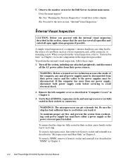
...supplies must have either a power supply or the power closeout panel installed. Verify that the chips are fully seated in Chapter 4. 2-4 Dell PowerEdge 6100/200 System Service Manual See "Running the System Diagnostics" found later in their sockets or connectors. To reseat a microprocessor, first remove it ...steps: 1. To maintain proper air flow and prevent the system from their power sources. Observe the monitor screen for the Dell Server Assistant main menu. A simple visual inspection of each power supply bay must be disconnected. Internal Visual Inspection CAUTION: Before you ...
...supplies must have either a power supply or the power closeout panel installed. Verify that the chips are fully seated in Chapter 4. 2-4 Dell PowerEdge 6100/200 System Service Manual See "Running the System Diagnostics" found later in their sockets or connectors. To reseat a microprocessor, first remove it ...steps: 1. To maintain proper air flow and prevent the system from their power sources. Observe the monitor screen for the Dell Server Assistant main menu. A simple visual inspection of each power supply bay must be disconnected. Internal Visual Inspection CAUTION: Before you ...
Service Manual
Page 42
... specific information about the system diagnostics. For instructions, see Chapter 11, "Getting Help," in the Installation and Troubleshooting Guide. 2-6 Dell PowerEdge 6100/200 System Service Manual See Chapter 5, "Running the System Diagnostics," in the Installation and Troubleshooting Guide for technical assistance. Getting Help If none of the troubleshooting ...
... specific information about the system diagnostics. For instructions, see Chapter 11, "Getting Help," in the Installation and Troubleshooting Guide. 2-6 Dell PowerEdge 6100/200 System Service Manual See Chapter 5, "Running the System Diagnostics," in the Installation and Troubleshooting Guide for technical assistance. Getting Help If none of the troubleshooting ...
Service Manual
Page 44
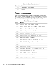
Beep Code 10 11 Table 3-1. Some of EISA ROM Failed 3-2 Dell PowerEdge 6100/200 System Service Manual Please Unlock It 0070 CMOS Time & Date Not Set 0080 Option ROM has bad checksum 0083 Shadow of PCI ROM Failed 0084 ...
Beep Code 10 11 Table 3-1. Some of EISA ROM Failed 3-2 Dell PowerEdge 6100/200 System Service Manual Please Unlock It 0070 CMOS Time & Date Not Set 0080 Option ROM has bad checksum 0083 Shadow of PCI ROM Failed 0084 ...