Dell PowerEdge Systems Microprocessor Upgrade Guide
Page 23
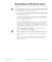
...the System Setup screens. Microprocessor Upgrade 1-19 The following steps. support.dell.com Dell PowerEdge Systems - To reassemble the system and perform verification checks, perform the following message appears: Second processor detected 2. Reset the chassis intrusion detector while in the System Setup program... your computer and peripherals to verify that the top line in this document. 1. Close the computer panel doors (for PowerEdge 4350 systems only) or replace the covers and front bezel, and reconnect your Installation and Troubleshooting Guide for accessing and modifying...
...the System Setup screens. Microprocessor Upgrade 1-19 The following steps. support.dell.com Dell PowerEdge Systems - To reassemble the system and perform verification checks, perform the following message appears: Second processor detected 2. Reset the chassis intrusion detector while in the System Setup program... your computer and peripherals to verify that the top line in this document. 1. Close the computer panel doors (for PowerEdge 4350 systems only) or replace the covers and front bezel, and reconnect your Installation and Troubleshooting Guide for accessing and modifying...

Dell PowerEdge 4350 System Upgrade Installation Guide
Page 7
...so by touching an unpainted metal surface on any of these precautions: To upgrade your PowerEdge 4350 system to a PowerEdge 6350 system, you continue to work inside your body. Static electricity can also take ...processor. As you need the following steps to prevent damage from electrostatic discharge (ESD): When unpacking a static-sensitive component from the antistatic packing material until you touch any system/component when servicing other systems/components in your computer. Handle all sensitive components in an antistatic container or packaging. Dell PowerEdge 4350...
...so by touching an unpainted metal surface on any of these precautions: To upgrade your PowerEdge 4350 system to a PowerEdge 6350 system, you continue to work inside your body. Static electricity can also take ...processor. As you need the following steps to prevent damage from electrostatic discharge (ESD): When unpacking a static-sensitive component from the antistatic packing material until you touch any system/component when servicing other systems/components in your computer. Handle all sensitive components in an antistatic container or packaging. Dell PowerEdge 4350...

Dell PowerEdge 4350 System Upgrade Installation Guide
Page 8
...computer chassis to put the parts removed from the system. Disconnect your computer and any peripherals. 2. Memory and processors for personal injury or shock. 4 Dell PowerEdge 4350 System Upgrade Installation Guide Provide for a suitable workspace that includes a place to unpack the upgrade kit, a ... Turn off your computer and peripherals from the computer. If an antistatic workbench pad is not available, be upgraded is a PowerEdge 4350 system. Also, disconnect any static electricity that might harm internal components. 3. Ground yourself by touching an unpainted metal surface on ...
...computer chassis to put the parts removed from the system. Disconnect your computer and any peripherals. 2. Memory and processors for personal injury or shock. 4 Dell PowerEdge 4350 System Upgrade Installation Guide Provide for a suitable workspace that includes a place to unpack the upgrade kit, a ... Turn off your computer and peripherals from the computer. If an antistatic workbench pad is not available, be upgraded is a PowerEdge 4350 system. Also, disconnect any static electricity that might harm internal components. 3. Ground yourself by touching an unpainted metal surface on ...

Dell PowerEdge 4350 System Upgrade Installation Guide
Page 9
To remove the PowerEdge 4350 system from the rack and place it extend out about a half centimeter (quarter of an inch). Disconnect all the way out (at the same time ... correctly oriented and aligned. Don't touch the components or contacts on a suitable work surface. Hold a component such as a processor chip by its edges, not by its metal mounting bracket. The computer is needed. Dell PowerEdge 4350 System Upgrade Installation Guide 5 Hold a card by its edges or by its pins. Loosen the thumbscrews securing the...
To remove the PowerEdge 4350 system from the rack and place it extend out about a half centimeter (quarter of an inch). Disconnect all the way out (at the same time ... correctly oriented and aligned. Don't touch the components or contacts on a suitable work surface. Hold a component such as a processor chip by its edges, not by its metal mounting bracket. The computer is needed. Dell PowerEdge 4350 System Upgrade Installation Guide 5 Hold a card by its edges or by its pins. Loosen the thumbscrews securing the...

Dell PowerEdge 4350 System Upgrade Installation Guide
Page 10
... doors interlock so that the keylock on the top of the system that provide access to the system board, memory, processors, and expansion cards. The right panel door provides access to the processor and memory (see Figure 1). Push the power supply handle down until its latch clicks into place, securing the power... here" symbol chassis slots (one each side) The computer has two panel doors on the right panel door secures both doors and the fan assembly. 6 Dell PowerEdge 4350 System Upgrade Installation Guide
... doors interlock so that the keylock on the top of the system that provide access to the system board, memory, processors, and expansion cards. The right panel door provides access to the processor and memory (see Figure 1). Push the power supply handle down until its latch clicks into place, securing the power... here" symbol chassis slots (one each side) The computer has two panel doors on the right panel door secures both doors and the fan assembly. 6 Dell PowerEdge 4350 System Upgrade Installation Guide

Dell PowerEdge 4350 System Upgrade Installation Guide
Page 13
...indicator so that the light- Place the hot-plug PCI gasket on the back. emitting diodes (LEDs) show through the holes in the panel. Dell PowerEdge 4350 System Upgrade Installation Guide 9 five are aligned with the corresponding holes in the gasket. The remaining screw is not used. Position the card on...card: a. Remove the seven screws that the two holes in the card are located on the chassis. 5. Position the new I /O panel to the processor(s). The end of the computer; To remove the fan assembly, grasp the recessed grip slot at the top of the fan assembly, press in on...
...indicator so that the light- Place the hot-plug PCI gasket on the back. emitting diodes (LEDs) show through the holes in the panel. Dell PowerEdge 4350 System Upgrade Installation Guide 9 five are aligned with the corresponding holes in the gasket. The remaining screw is not used. Position the card on...card: a. Remove the seven screws that the two holes in the card are located on the chassis. 5. Position the new I /O panel to the processor(s). The end of the computer; To remove the fan assembly, grasp the recessed grip slot at the top of the fan assembly, press in on...

Dell PowerEdge 4350 System Upgrade Installation Guide
Page 17
you must purchase them separately. NOTE: Memory and processors for the PowerEdge 6350 system board are not supplied in the upgrade kit; Dell PowerEdge 4350 System Upgrade Installation Guide 13 Ultra2/LVD SCSI connector (PRIMARY SCSI-B) Ultra/Narrow SCSI connector (...interface connector (FLOPPY) power input connector (POWER2) power input connector (POWER3) Dell Remote Assistant Card connector (SVR_MGT) front of system board battery connector (BATTERY) Ultra2/LVD SCSI connector (PRIMARY SCSI-A) processors (4) (PROC_1 [top] through PROC_4) speed and configuration jumpers keyboard and mouse...
you must purchase them separately. NOTE: Memory and processors for the PowerEdge 6350 system board are not supplied in the upgrade kit; Dell PowerEdge 4350 System Upgrade Installation Guide 13 Ultra2/LVD SCSI connector (PRIMARY SCSI-B) Ultra/Narrow SCSI connector (...interface connector (FLOPPY) power input connector (POWER2) power input connector (POWER3) Dell Remote Assistant Card connector (SVR_MGT) front of system board battery connector (BATTERY) Ultra2/LVD SCSI connector (PRIMARY SCSI-A) processors (4) (PROC_1 [top] through PROC_4) speed and configuration jumpers keyboard and mouse...

Dell PowerEdge 4350 System Upgrade Installation Guide
Page 18
Carefully remove the system board from its packaging material. 2. 1. Verify that the jumpers are set as shown in Figure 7 except for the speed jumper, which should be set to the speed of the processor(s). jumpered unjumpered 14 Dell PowerEdge 4350 System Upgrade Installation Guide
Carefully remove the system board from its packaging material. 2. 1. Verify that the jumpers are set as shown in Figure 7 except for the speed jumper, which should be set to the speed of the processor(s). jumpered unjumpered 14 Dell PowerEdge 4350 System Upgrade Installation Guide

Dell PowerEdge 4350 System Upgrade Installation Guide
Page 20
...see Figure 9). 16 Dell PowerEdge 4350 System Upgrade Installation Guide NOTE: The system cables that the speed jumper is set to "Upgrading the Microprocessor or Installing an Additional Microprocessor" in Chapter 8 of the system's Installation and Troubleshooting Guide. Install the processor(s). The terminator cartridges... are supplied separately from the SCSI backplane to the connector labeled "SEC- Connect the 68-pin data cable in any unoccupied processor sockets. To reinstall the system cables, perform the following steps: 1. ONDARY SCSI" on the system board (see Figure 7)....
...see Figure 9). 16 Dell PowerEdge 4350 System Upgrade Installation Guide NOTE: The system cables that the speed jumper is set to "Upgrading the Microprocessor or Installing an Additional Microprocessor" in Chapter 8 of the system's Installation and Troubleshooting Guide. Install the processor(s). The terminator cartridges... are supplied separately from the SCSI backplane to the connector labeled "SEC- Connect the 68-pin data cable in any unoccupied processor sockets. To reinstall the system cables, perform the following steps: 1. ONDARY SCSI" on the system board (see Figure 7)....

Dell PowerEdge 4350 System Upgrade Installation Guide
Page 28
..., and set the system between the rack slides. 2. Remove the protective backing from the new system badge and carefully press it into the rack. 24 Dell PowerEdge 4350 System Upgrade Installation Guide Reattach the cables. Install the new system and expansion card information label on the inside of the computer, perform the following... that the keylock secures both doors properly. Remove the backing from the label. 2. See the system's User's Guide for more information. 3. Install the memory and processor information label on the front bezel of the left door.
..., and set the system between the rack slides. 2. Remove the protective backing from the new system badge and carefully press it into the rack. 24 Dell PowerEdge 4350 System Upgrade Installation Guide Reattach the cables. Install the new system and expansion card information label on the inside of the computer, perform the following... that the keylock secures both doors properly. Remove the backing from the label. 2. See the system's User's Guide for more information. 3. Install the memory and processor information label on the front bezel of the left door.

Dell PowerEdge 4350 System Upgrade Installation Guide
Page 29
...If your organization assign to the system for the new system board. Dell PowerEdge 4350 System Upgrade Installation Guide 25 Run the Asset Tag utility. The Asset Tag utility allows you to recognize multiple processors. If your operating system to enter a unique asset tag number that ... refer to Chapter 2, "Using the Dell Server Assistant CD," in the upgrade kit to your system, perform the following steps: 1. After you must upgrade your original PowerEdge 4350 system was a single-processor system and the upgraded system has two or more processors, you start the system, flash the...
...If your organization assign to the system for the new system board. Dell PowerEdge 4350 System Upgrade Installation Guide 25 Run the Asset Tag utility. The Asset Tag utility allows you to recognize multiple processors. If your operating system to enter a unique asset tag number that ... refer to Chapter 2, "Using the Dell Server Assistant CD," in the upgrade kit to your system, perform the following steps: 1. After you must upgrade your original PowerEdge 4350 system was a single-processor system and the upgraded system has two or more processors, you start the system, flash the...

Dell PowerEdge 4350 System Upgrade Installation Guide
Page 31
You have the following excess parts after you upgrade your system: Dell PowerEdge 4350 system board, with installed processor(s) and memory System board tray Two SCSI cables Two DC power cables I/O panel External SCSI port filler bracket Air dam shroud (if one was previously installed) Two screws You do not need to return these parts to Dell. Dell PowerEdge 4350 System Upgrade Installation Guide 27
You have the following excess parts after you upgrade your system: Dell PowerEdge 4350 system board, with installed processor(s) and memory System board tray Two SCSI cables Two DC power cables I/O panel External SCSI port filler bracket Air dam shroud (if one was previously installed) Two screws You do not need to return these parts to Dell. Dell PowerEdge 4350 System Upgrade Installation Guide 27


