
Installing a SATA Optical Drive
Page 9
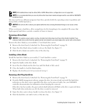
... Reconnect the system to the CD/TBU connector on the system and attached peripherals. See Figure 1-5. - For a PowerEdge 2900, use the SATA_D connector. For a PowerEdge 2900 system, connect to power and turn on the system backplane. Installing a SATA Optical Drive 9 Installing the SATA Optical Drive - See "Closing the System" in the optical drive...
... Reconnect the system to the CD/TBU connector on the system and attached peripherals. See Figure 1-5. - For a PowerEdge 2900, use the SATA_D connector. For a PowerEdge 2900 system, connect to power and turn on the system backplane. Installing a SATA Optical Drive 9 Installing the SATA Optical Drive - See "Closing the System" in the optical drive...

Installing a SATA Optical Drive
Page 10
SATA Cable Routing in your Hardware Owner's Manual. 10 Reconnect the system to the SAS controller daughter card. 9 Close the system. See "Closing the System" in a PowerEdge 2900 or 1900 3 2 4 5 1 1 optical drive 3 SATA data cable 5 SATA power connector on SAS backplane (PowerEdge 2900 only) 2 SATA power cable 4 SATA connector on system board 8 Reconnect the cables to power and turn on the system and attached peripherals. 10 Installing a SATA Optical Drive Figure 1-5.
SATA Cable Routing in your Hardware Owner's Manual. 10 Reconnect the system to the SAS controller daughter card. 9 Close the system. See "Closing the System" in a PowerEdge 2900 or 1900 3 2 4 5 1 1 optical drive 3 SATA data cable 5 SATA power connector on SAS backplane (PowerEdge 2900 only) 2 SATA power cable 4 SATA connector on system board 8 Reconnect the cables to power and turn on the system and attached peripherals. 10 Installing a SATA Optical Drive Figure 1-5.
Information Update
Page 4
3.5-Inch Chassis Update 13 Front Features and Indicators 13 Mixed SAS/SATA Hard Drive Configuration (3.5-Inch Drives Only 15 Removing a 3.5-Inch Drive Blank 15 Installing a 3.5-Inch Drive Blank 15 Removing the SAS/SATA Backplane Board . . . . 16 Installing the SAS Backplane Board 18 SAS/SATA Backplane Board Connectors . . . . . 19 4 Contents
3.5-Inch Chassis Update 13 Front Features and Indicators 13 Mixed SAS/SATA Hard Drive Configuration (3.5-Inch Drives Only 15 Removing a 3.5-Inch Drive Blank 15 Installing a 3.5-Inch Drive Blank 15 Removing the SAS/SATA Backplane Board . . . . 16 Installing the SAS Backplane Board 18 SAS/SATA Backplane Board Connectors . . . . . 19 4 Contents
Information Update
Page 16
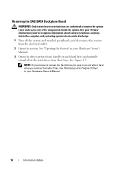
... remove the hard drives, be sure to remove the system cover and access any of the hard drives from their bays. Removing the SAS/SATA Backplane Board WARNING: Only trained service technicians are authorized to record which hard drive you remove from which bay. See "Removing a Hot-Plug Hard Drive" in...
... remove the hard drives, be sure to remove the system cover and access any of the hard drives from their bays. Removing the SAS/SATA Backplane Board WARNING: Only trained service technicians are authorized to record which hard drive you remove from which bay. See "Removing a Hot-Plug Hard Drive" in...
Information Update
Page 17
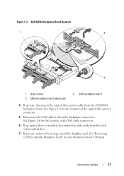
... 4 If present, disconnect the optical drive power cable from the backplane connectors. See "Removing a SAS Controller Daughter Card" in your Hardware Owner's Manual. Figure 1-3. See Figure 1-4 for the location of the SAS cable connectors. 6 If an ...optical drive is installed, disconnect the data cable from the back of the optical drive power connector. 5 Disconnect the SAS cable(s) from the SAS/SATA backplane board. See Figure 1-4 for the location of the optical drive. 7 If present, remove the storage controller daughter card. Information Update 17
... 4 If present, disconnect the optical drive power cable from the backplane connectors. See "Removing a SAS Controller Daughter Card" in your Hardware Owner's Manual. Figure 1-3. See Figure 1-4 for the location of the SAS cable connectors. 6 If an ...optical drive is installed, disconnect the data cable from the back of the optical drive power connector. 5 Disconnect the SAS cable(s) from the SAS/SATA backplane board. See Figure 1-4 for the location of the optical drive. 7 If present, remove the storage controller daughter card. Information Update 17
Information Update
Page 18
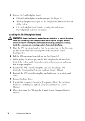
...system until it stops, then release the release pin and ensure that the securing tabs on the drive cage are authorized to the backplane board. See "Installing the Optical Drive" in your Product Information Guide for complete information about safety precautions, working inside the system.... b While pulling the release pin, tilt the backplane board toward the front of the system. See "Installing a SAS Controller Daughter Card" in your Hardware Owner's Manual. 18 Information Update See...
...system until it stops, then release the release pin and ensure that the securing tabs on the drive cage are authorized to the backplane board. See "Installing the Optical Drive" in your Product Information Guide for complete information about safety precautions, working inside the system.... b While pulling the release pin, tilt the backplane board toward the front of the system. See "Installing a SAS Controller Daughter Card" in your Hardware Owner's Manual. 18 Information Update See...
Information Update
Page 19
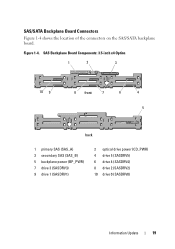
SAS Backplane Board Components: 3.5-inch x4 Option 1 2 3 10 9 8 front 7 6 4 5 back 1 primary SAS (SAS_A) 3 secondary SAS (SAS_B) 5 backplane power (BP_PWR) 7 drive 3 (SASDRV3) 9 drive 1 (SASDRV1) 2 optical drive power (CD_PWR) 4 drive 5 (SASDRV5) 6 drive 4 (SASDRV4) 8 drive 2 (SASDRV2) 10 drive 0 (SASDRV0) Information Update 19 SAS/SATA Backplane Board Connectors Figure 1-4 shows the location of the connectors on the SAS/SATA backplane board. Figure 1-4.
SAS Backplane Board Components: 3.5-inch x4 Option 1 2 3 10 9 8 front 7 6 4 5 back 1 primary SAS (SAS_A) 3 secondary SAS (SAS_B) 5 backplane power (BP_PWR) 7 drive 3 (SASDRV3) 9 drive 1 (SASDRV1) 2 optical drive power (CD_PWR) 4 drive 5 (SASDRV5) 6 drive 4 (SASDRV4) 8 drive 2 (SASDRV2) 10 drive 0 (SASDRV0) Information Update 19 SAS/SATA Backplane Board Connectors Figure 1-4 shows the location of the connectors on the SAS/SATA backplane board. Figure 1-4.

Hardware Owner's Manual
Page 6
... Center Riser Board 104 Sideplane Board 105 Removing the Sideplane Board 105 Installing the Sideplane Board 107 SAS/SATA Backplane Board 107 Removing the SAS/SATA Backplane Board 107 Installing the SAS/SATA Backplane Board 108 Control Panel Assembly (Service-only Procedure 109 Removing the Control Panel Assembly 109 Installing the Control Panel...
... Center Riser Board 104 Sideplane Board 105 Removing the Sideplane Board 105 Installing the Sideplane Board 107 SAS/SATA Backplane Board 107 Removing the SAS/SATA Backplane Board 107 Installing the SAS/SATA Backplane Board 108 Control Panel Assembly (Service-only Procedure 109 Removing the Control Panel Assembly 109 Installing the Control Panel...
Hardware Owner's Manual
Page 8
... Testing 136 Selecting Diagnostics Options 137 Viewing Information and Results 137 6 Jumpers and Connectors 139 System Board Jumpers 139 System Board Connectors 141 SAS/SATA Backplane Board Connectors 143 Sideplane Board Connectors 144 Expansion-Card Riser-Board Components and PCIe Buses 144 Disabling a Forgotten Password 145 7 Getting Help 147 Technical Assistance...
... Testing 136 Selecting Diagnostics Options 137 Viewing Information and Results 137 6 Jumpers and Connectors 139 System Board Jumpers 139 System Board Connectors 141 SAS/SATA Backplane Board Connectors 143 Sideplane Board Connectors 144 Expansion-Card Riser-Board Components and PCIe Buses 144 Disabling a Forgotten Password 145 7 Getting Help 147 Technical Assistance...
Hardware Owner's Manual
Page 51
... • Optical, diskette, and tape drives • System memory • Processors • System battery • Expansion-card riser boards • Sideplane board • SAS/SATA Backplane board • Control panel assembly • System board Recommended Tools You may need the following items to perform the procedures in this section: • Key...
... • Optical, diskette, and tape drives • System memory • Processors • System battery • Expansion-card riser boards • Sideplane board • SAS/SATA Backplane board • Control panel assembly • System board Recommended Tools You may need the following items to perform the procedures in this section: • Key...
Hardware Owner's Manual
Page 52
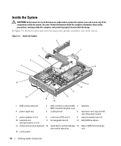
... for optional diskette 15 drive and/or tape drive sideplane expansion-card cage and left riser (PCIe slots 2 and 3) memory modules (up to 8) SAS/SATA backplane SAS or SATA hard drives (up to 8) 52 Installing System Components Inside the System CAUTION: Only trained service technicians are removed to provide an interior...
... for optional diskette 15 drive and/or tape drive sideplane expansion-card cage and left riser (PCIe slots 2 and 3) memory modules (up to 8) SAS/SATA backplane SAS or SATA hard drives (up to 8) 52 Installing System Components Inside the System CAUTION: Only trained service technicians are removed to provide an interior...
Hardware Owner's Manual
Page 53
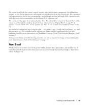
The optical drive connects to the controllers on the system board through the SAS/SATA backplane board. For more information, see "Hard Drives" on page 56 and "SAS Controller Daughter Card" on the bezel restricts access to eight 2.5-inch SAS or ...
The optical drive connects to the controllers on the system board through the SAS/SATA backplane board. For more information, see "Hard Drives" on page 56 and "SAS Controller Daughter Card" on the bezel restricts access to eight 2.5-inch SAS or ...

Hardware Owner's Manual
Page 56
... of the system and offset the cover slightly back so that the host adapter is configured correctly to the system board through the SAS/SATA backplane board. Hard drives are supplied in special hotpluggable drive carriers that fit in the hard-drive bays. All drives connect to support hotplug drive removal...
... of the system and offset the cover slightly back so that the host adapter is configured correctly to the system board through the SAS/SATA backplane board. Hard drives are supplied in special hotpluggable drive carriers that fit in the hard-drive bays. All drives connect to support hotplug drive removal...
Hardware Owner's Manual
Page 57
... blank is being formatted. You may need to use only drives that you format a hard drive, allow enough time for use with the SAS/SATA backplane board. When you use different programs than those provided with a drive blank. Installing System Components 57 NOTE: It is free of hours to release the...
... blank is being formatted. You may need to use only drives that you format a hard drive, allow enough time for use with the SAS/SATA backplane board. When you use different programs than those provided with a drive blank. Installing System Components 57 NOTE: It is free of hours to release the...

Hardware Owner's Manual
Page 59
... the hard drive from the carrier. Installing a Hard Drive Into a Drive Carrier 1 Insert the hard drive into the drive bay until the carrier contacts the backplane. Replacing a Hard-Drive Carrier Removing a Hard Drive From a Hard-Drive Carrier Remove the four screws from the slide rails on the hard drive carrier. c Close...
... the hard drive from the carrier. Installing a Hard Drive Into a Drive Carrier 1 Insert the hard drive into the drive bay until the carrier contacts the backplane. Replacing a Hard-Drive Carrier Removing a Hard Drive From a Hard-Drive Carrier Remove the four screws from the slide rails on the hard drive carrier. c Close...

Hardware Owner's Manual
Page 66
...) SAS controller daughter card socket SAS connector(s) (1 or 2) 5 Attach the interface cable(s) to the SAS controller daughter card and to the backplane. • For a non-RAID SAS controller (with dual connectors), attach the first interface cable to connector 0 on the SAS RAID controller and... to the SAS_A connector on the backplane. See Figure 3-11. 66 Installing System Components Figure 3-9. Attach the second interface cable to connector 1 on the backplane. See Figure 3-10. • For a SAS RAID controller (with a single connector...
...) SAS controller daughter card socket SAS connector(s) (1 or 2) 5 Attach the interface cable(s) to the SAS controller daughter card and to the backplane. • For a non-RAID SAS controller (with dual connectors), attach the first interface cable to connector 0 on the SAS RAID controller and... to the SAS_A connector on the backplane. See Figure 3-11. 66 Installing System Components Figure 3-9. Attach the second interface cable to connector 1 on the backplane. See Figure 3-10. • For a SAS RAID controller (with a single connector...

Hardware Owner's Manual
Page 67
SAS Controller Daughter Card Cabling 2 1 3 4 1 SAS controller daughter card 2 SAS controller 0 4 SAS/SATA backplane 3 backplane connector A (SAS_A) Installing System Components 67 See "Installing a RAID Battery" on page 69. 6 If you are installing a SAS RAID controller, install the RAID battery. Figure 3-10.
SAS Controller Daughter Card Cabling 2 1 3 4 1 SAS controller daughter card 2 SAS controller 0 4 SAS/SATA backplane 3 backplane connector A (SAS_A) Installing System Components 67 See "Installing a RAID Battery" on page 69. 6 If you are installing a SAS RAID controller, install the RAID battery. Figure 3-10.

Hardware Owner's Manual
Page 68
See Figure 3-9. 68 Installing System Components SAS RAID Controller Daughter Card Cabling 3 2 1 4 5 6 1 SAS RAID controller daughter 2 card 4 backplane connector A 5 (SAS_A) SAS controller 0 backplane connector B (SAS_B) 3 SAS controller 1 6 SAS/SATA backplane Removing a SAS Controller Daughter Card 1 Disconnect any battery connectors if applicable. 2 Disconnect any SAS cables from the card. 3 Gently press down on the release...
See Figure 3-9. 68 Installing System Components SAS RAID Controller Daughter Card Cabling 3 2 1 4 5 6 1 SAS RAID controller daughter 2 card 4 backplane connector A 5 (SAS_A) SAS controller 0 backplane connector B (SAS_B) 3 SAS controller 1 6 SAS/SATA backplane Removing a SAS Controller Daughter Card 1 Disconnect any battery connectors if applicable. 2 Disconnect any SAS cables from the card. 3 Gently press down on the release...

Hardware Owner's Manual
Page 89
.... Removing and Replacing the Tape Drive Cable Retention Bracket The optional SCSI tape drive connects to its electrical outlet and turn the system on the backplane. Removing and Installing an Internal Tape Drive 1 2 3 4 1 tape drive rails (2) 4 screws (4) 2 tape drive 3 rail release tabs (2) 8 Route the tape drive's interface cable through an expansion...
.... Removing and Replacing the Tape Drive Cable Retention Bracket The optional SCSI tape drive connects to its electrical outlet and turn the system on the backplane. Removing and Installing an Internal Tape Drive 1 2 3 4 1 tape drive rails (2) 4 screws (4) 2 tape drive 3 rail release tabs (2) 8 Route the tape drive's interface cable through an expansion...

Hardware Owner's Manual
Page 107
...collars connect with the two pins on the system board. See "Closing the System" on page 68. 7 Remove the SAS/SATA backplane board: a Pull the backplane board release pin. See "Opening the System" on page 82. 4 Remove the hard drives. See Figure 3-32. 3 Reattach any... cables to the sideplane board. 4 If applicable, replace the storage controller daughter card. c Lift the backplane board from its securing tabs and remove the backplane board from the electrical outlet. 2 Insert the sideplane board into the system board connector. See "Removing a SAS Controller Daughter...
...collars connect with the two pins on the system board. See "Closing the System" on page 68. 7 Remove the SAS/SATA backplane board: a Pull the backplane board release pin. See "Opening the System" on page 82. 4 Remove the hard drives. See Figure 3-32. 3 Reattach any... cables to the sideplane board. 4 If applicable, replace the storage controller daughter card. c Lift the backplane board from its securing tabs and remove the backplane board from the electrical outlet. 2 Insert the sideplane board into the system board connector. See "Removing a SAS Controller Daughter...


