Getting Started Guide
Page 6
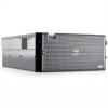
... with an ATI ES1000, 33-MHz PCI video controller. Expansion-card slots accommodate full-height, full-length expansion cards. See support.dell.com for the latest support information about specific features, see "Technical Specifications" on the front and back panels. Maximum resolution is...rates. • Six USB 2.0-compliant connectors (two on the front and four on the back) capable of cache memory and a RAID battery. The systems management circuitry works in conjunction with the systems management software. • Standard baseboard management controller with serial access. • Back...
... with an ATI ES1000, 33-MHz PCI video controller. Expansion-card slots accommodate full-height, full-length expansion cards. See support.dell.com for the latest support information about specific features, see "Technical Specifications" on the front and back panels. Maximum resolution is...rates. • Six USB 2.0-compliant connectors (two on the front and four on the back) capable of cache memory and a RAID battery. The systems management circuitry works in conjunction with the systems management software. • Standard baseboard management controller with serial access. • Back...

Getting Started Guide
Page 13
... and over the entire system ambient operating range, the inrush current may reach 55 A per power supply) Wattage Voltage Heat dissipation Maximum inrush current Batteries System battery RAID battery (optional) Physical Rack Height Width Two TOE-capable RJ-45 (for 10 ms or less CR 2032 3.0-V lithium ion coin cell 4.1-V lithium ion 21...
... and over the entire system ambient operating range, the inrush current may reach 55 A per power supply) Wattage Voltage Heat dissipation Maximum inrush current Batteries System battery RAID battery (optional) Physical Rack Height Width Two TOE-capable RJ-45 (for 10 ms or less CR 2032 3.0-V lithium ion coin cell 4.1-V lithium ion 21...

Hardware Owner's Manual (PDF)
Page 5
... Diskette Drive 74 Removing the Diskette Drive 74 Installing the Diskette Drive Into the Drive Carrier 76 Installing the Diskette Drive 76 System Battery 77 Replacing the System Battery 77 Cooling Shroud 79 Removing the Cooling Shroud 79 Installing the Cooling Shroud 81 Fan Brackets 81 Removing the Center Fan Bracket 81...
... Diskette Drive 74 Removing the Diskette Drive 74 Installing the Diskette Drive Into the Drive Carrier 76 Installing the Diskette Drive 76 System Battery 77 Replacing the System Battery 77 Cooling Shroud 79 Removing the Cooling Shroud 79 Installing the Cooling Shroud 81 Fan Brackets 81 Removing the Center Fan Bracket 81...

Hardware Owner's Manual (PDF)
Page 6
... Flex Bay Drive Bracket 94 Installing the 1x2 Flex Bay Drive Bracket 95 SAS Controller Daughter Card 96 Replacing the SAS RAID Controller Daughter Card Battery 96 Removing the SAS Controller Daughter Card 97 Installing the SAS Controller Daughter Card 99 Cabling the SAS Backplane Boards 99 Cable Requirements 99 Cabling...
... Flex Bay Drive Bracket 94 Installing the 1x2 Flex Bay Drive Bracket 95 SAS Controller Daughter Card 96 Replacing the SAS RAID Controller Daughter Card Battery 96 Removing the SAS Controller Daughter Card 97 Installing the SAS Controller Daughter Card 99 Cabling the SAS Backplane Boards 99 Cable Requirements 99 Cabling...

Hardware Owner's Manual (PDF)
Page 7
... Basic I/O Functions 118 Troubleshooting a Serial I/O Device 119 Troubleshooting a USB Device 119 Troubleshooting a NIC 120 Troubleshooting a Wet System 120 Troubleshooting a Damaged System 121 Troubleshooting the System Battery 122 Troubleshooting Power Supplies 122 Troubleshooting System Cooling Problems 123 Troubleshooting a Fan 123 Troubleshooting System Memory 124 Troubleshooting a Diskette Drive 126 Troubleshooting an Optical Drive...
... Basic I/O Functions 118 Troubleshooting a Serial I/O Device 119 Troubleshooting a USB Device 119 Troubleshooting a NIC 120 Troubleshooting a Wet System 120 Troubleshooting a Damaged System 121 Troubleshooting the System Battery 122 Troubleshooting Power Supplies 122 Troubleshooting System Cooling Problems 123 Troubleshooting a Fan 123 Troubleshooting System Memory 124 Troubleshooting a Diskette Drive 126 Troubleshooting an Optical Drive...
Hardware Owner's Manual (PDF)
Page 19
... under the following conditions: "Using the System Setup • The system is off and active POST errors are displayed. RAID battery is no longer fan- Processor # VCORE voltage regulator has failed. Memory has exceeded acceptable See "Troubleshooting System temperature and has... range. Cooling Problems" on page 122. disabled to prevent damage to "Replacing the SAS RAID thermal issues. Battery" on page 123. Controller Daughter Card Battery" on page 96, and "Troubleshooting System Cooling Problems" on page 147. Specified voltage regulator has See "Getting...
... under the following conditions: "Using the System Setup • The system is off and active POST errors are displayed. RAID battery is no longer fan- Processor # VCORE voltage regulator has failed. Memory has exceeded acceptable See "Troubleshooting System temperature and has... range. Cooling Problems" on page 122. disabled to prevent damage to "Replacing the SAS RAID thermal issues. Battery" on page 123. Controller Daughter Card Battery" on page 96, and "Troubleshooting System Cooling Problems" on page 147. Specified voltage regulator has See "Getting...

Hardware Owner's Manual (PDF)
Page 25
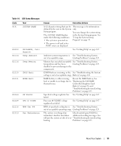
... mirroring because it has Memory" on the Northbound side has failed. See "Troubleshooting System Memory" on page 124. Information only. See battery has less than 24 hours of events, and is full of "Replacing the SAS RAID charge left. See "Troubleshooting System Memory" on...errors. Table 1-6. "## & ##" represents the DIMM pair implicated by the BIOS. I1911 >3 ERRs Chk Log LCD overflow message. Controller Daughter Card Battery" on the LCD. NOTE: For the full name of an abbreviation or acronym used in this table, see the "Glossary" on the A maximum...
... mirroring because it has Memory" on the Northbound side has failed. See "Troubleshooting System Memory" on page 124. Information only. See battery has less than 24 hours of events, and is full of "Replacing the SAS RAID charge left. See "Troubleshooting System Memory" on...errors. Table 1-6. "## & ##" represents the DIMM pair implicated by the BIOS. I1911 >3 ERRs Chk Log LCD overflow message. Controller Daughter Card Battery" on the LCD. NOTE: For the full name of an abbreviation or acronym used in this table, see the "Glossary" on the A maximum...
Hardware Owner's Manual (PDF)
Page 32
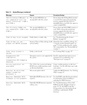
...The following DIMMs are The specified DIMM(s) are incompatible with your Dell sales agent to ensure compatibility. Time-of -day not set please run SETUP program Incorrect Time or Date settings; See "System Battery" on the boot hard drive. Warning: Embedded RAID error!... came with the system. Warning: Embedded RAID firmware is used . DIMM y Ensure that only Dell-qualified memory is used . If the problem persists, replace the system battery. Timer chip counter 2 failed Faulty system board. See the RAID controller documentation for information about ...
...The following DIMMs are The specified DIMM(s) are incompatible with your Dell sales agent to ensure compatibility. Time-of -day not set please run SETUP program Incorrect Time or Date settings; See "System Battery" on the boot hard drive. Warning: Embedded RAID error!... came with the system. Warning: Embedded RAID firmware is used . DIMM y Ensure that only Dell-qualified memory is used . If the problem persists, replace the system battery. Timer chip counter 2 failed Faulty system board. See the RAID controller documentation for information about ...

Hardware Owner's Manual (PDF)
Page 49
... following system components: • Hot-plug hard drives • Power supplies • Cooling fans • Expansion cards • Tape, optical, and diskette drives • System battery • System memory • RAC card • Microprocessors • SAS backplane board • SAS controller daughter card • Control panel assembly • System board •...
... following system components: • Hot-plug hard drives • Power supplies • Cooling fans • Expansion cards • Tape, optical, and diskette drives • System battery • System memory • RAC card • Microprocessors • SAS backplane board • SAS controller daughter card • Control panel assembly • System board •...
Hardware Owner's Manual (PDF)
Page 77
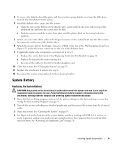
... the system: a Align the slots on the bottom of the diskette drive carrier with the system battery. See "Using the System Setup Program" on page 35. 2 Turn off the system, including any of the system battery and then, starting with PCI slot 6, remove as many expansion cards as you need to create... "Closing the System" on page 70. See "Opening the System" on the rear of the peripheral bay and lower the carrier unto the tabs. System Battery Replacing the System Battery CAUTION: Only trained service technicians are authorized to the SAS controller daughter card. 10 Close the system.
... the system: a Align the slots on the bottom of the diskette drive carrier with the system battery. See "Using the System Setup Program" on page 35. 2 Turn off the system, including any of the system battery and then, starting with PCI slot 6, remove as many expansion cards as you need to create... "Closing the System" on page 70. See "Opening the System" on the rear of the peripheral bay and lower the carrier unto the tabs. System Battery Replacing the System Battery CAUTION: Only trained service technicians are authorized to the SAS controller daughter card. 10 Close the system.

Hardware Owner's Manual (PDF)
Page 78
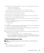
... the positive side of the connector and pry it up out of the securing tabs at the positive side of the connector. b Hold the battery with the side labeled "+" facing up , and slide it snaps into place. 8 Replace all the expansion cards you must firmly support the ...connector while installing or removing a battery. a Support the battery connector by pressing down into the connector until it under the securing tabs at the negative side of the connector. See Figure 3-19. 7 Install...
... the positive side of the connector and pry it up out of the securing tabs at the positive side of the connector. b Hold the battery with the side labeled "+" facing up , and slide it snaps into place. 8 Replace all the expansion cards you must firmly support the ...connector while installing or removing a battery. a Support the battery connector by pressing down into the connector until it under the securing tabs at the negative side of the connector. See Figure 3-19. 7 Install...

Hardware Owner's Manual (PDF)
Page 96
...provides the SAS storage subsystem for your SAS RAID controller daughter card. For more information, see the documentation that the battery is aligned and fully seated into the battery bay, ensuring that came with your system's internal hard drives. 6 Connect the SAS cables to the flex bay... (INT STORAGE) for the location of the SAS_B connector on the daughter card and pulling the battery cable free. Replacing the SAS RAID Controller Daughter Card Battery 1 Disconnect the battery cable from the expansion-bay bracket by releasing the tab on the cable connector on the 1x8 backplane...
...provides the SAS storage subsystem for your SAS RAID controller daughter card. For more information, see the documentation that the battery is aligned and fully seated into the battery bay, ensuring that came with your system's internal hard drives. 6 Connect the SAS cables to the flex bay... (INT STORAGE) for the location of the SAS_B connector on the daughter card and pulling the battery cable free. Replacing the SAS RAID Controller Daughter Card Battery 1 Disconnect the battery cable from the expansion-bay bracket by releasing the tab on the cable connector on the 1x8 backplane...

Hardware Owner's Manual (PDF)
Page 97
... from the controller card by releasing the tab on the cable connector on the daughter card and pulling the battery cable free. 2 Push outward on the plastic guide rails and gently pull up on the card edges until the card...clears the socket on the system board. Replacing a SAS RAID Controller Daughter Card Battery 2 3 1 7 6 3 5 4 1 SAS RAID controller daughter 2 RAID battery cable card 4 routing hole for RAID battery 5 expansion-bay bracket cable 7 RAID battery 3 connector release tab 6 battery bay Removing the SAS Controller Daughter Card The following procedure applies to either a ...
... from the controller card by releasing the tab on the cable connector on the daughter card and pulling the battery cable free. 2 Push outward on the plastic guide rails and gently pull up on the card edges until the card...clears the socket on the system board. Replacing a SAS RAID Controller Daughter Card Battery 2 3 1 7 6 3 5 4 1 SAS RAID controller daughter 2 RAID battery cable card 4 routing hole for RAID battery 5 expansion-bay bracket cable 7 RAID battery 3 connector release tab 6 battery bay Removing the SAS Controller Daughter Card The following procedure applies to either a ...

Hardware Owner's Manual (PDF)
Page 98
...to 1x8 2 SAS connector 1 (SAS RAID 3 SAS controller daughter card backplane SAS_A connector) only) (out to replace the SAS daughter card battery, see "Replacing the SAS RAID Controller Daughter Card Battery" on page 96. Figure 3-28. If you pull the SAS controller daughter card upward from the rails. 3 Continue to hold the... guide rails outward as you need to 1x8 backplane SAS_B connector or 1x2 SAS_B_IN connector) 4 RAID battery cable (SAS RAID 5 daughter card slot socket only) 6 slide rails (2) 98 Installing System Components
...to 1x8 2 SAS connector 1 (SAS RAID 3 SAS controller daughter card backplane SAS_A connector) only) (out to replace the SAS daughter card battery, see "Replacing the SAS RAID Controller Daughter Card Battery" on page 96. Figure 3-28. If you pull the SAS controller daughter card upward from the rails. 3 Continue to hold the... guide rails outward as you need to 1x8 backplane SAS_B connector or 1x2 SAS_B_IN connector) 4 RAID battery cable (SAS RAID 5 daughter card slot socket only) 6 slide rails (2) 98 Installing System Components

Hardware Owner's Manual (PDF)
Page 99
.... Table 3-2. Installing System Components 99 See Figure 3-29. See Figure 3-14 and Figure 3-28. 3 If present, connect the battery cable to the battery cable connector on the SAS backplane board. Cable Requirements Configuration SAS controller SAS RAID controller /no 1x2 flex bay backplane SAS RAID controller...For a system with the slide rails on the system board. If you need to replace the SAS daughter card battery, see "Replacing the SAS RAID Controller Daughter Card Battery" on your SAS storage, the number of cables required, and the number of the DIMM socket on the daughter ...
.... Table 3-2. Installing System Components 99 See Figure 3-29. See Figure 3-14 and Figure 3-28. 3 If present, connect the battery cable to the battery cable connector on the SAS backplane board. Cable Requirements Configuration SAS controller SAS RAID controller /no 1x2 flex bay backplane SAS RAID controller...For a system with the slide rails on the system board. If you need to replace the SAS daughter card battery, see "Replacing the SAS RAID Controller Daughter Card Battery" on your SAS storage, the number of cables required, and the number of the DIMM socket on the daughter ...

Hardware Owner's Manual (PDF)
Page 122
... of the components inside the computer and protecting against electrostatic discharge. 1 Run the appropriate online diagnostics test. See "Replacing the System Battery" on page 135. 2 Locate the faulty power supply. Before performing any of time (for complete information about safety precautions, working... on page 77. See "Using the System Setup Program" on page 147. The power supply's fault indicator is caused by a defective battery. See "Power Indicator Codes" on the system. 4 Enter the System Setup program. NOTE: Some software may lose its system configuration information...
... of the components inside the computer and protecting against electrostatic discharge. 1 Run the appropriate online diagnostics test. See "Replacing the System Battery" on page 135. 2 Locate the faulty power supply. Before performing any of time (for complete information about safety precautions, working... on page 77. See "Using the System Setup Program" on page 147. The power supply's fault indicator is caused by a defective battery. See "Power Indicator Codes" on the system. 4 Enter the System Setup program. NOTE: Some software may lose its system configuration information...
Hardware Owner's Manual (PDF)
Page 131
... daughter card, the SAS backplane board and, if applicable, the 1x2 expansion backplane. 12 Close the system. If replacing the battery does not solve the problem, see the documentation for information about configuration settings. 4 Check the configuration settings, make any necessary ...SAS RAID controller See the controller's documentation for your operating system and the expansion card. See "Replacing the SAS RAID Controller Daughter Card Battery" on the system and attached peripherals. Problem • Error message indicates a problem with an expansion card. • Expansion card ...
... daughter card, the SAS backplane board and, if applicable, the 1x2 expansion backplane. 12 Close the system. If replacing the battery does not solve the problem, see the documentation for information about configuration settings. 4 Check the configuration settings, make any necessary ...SAS RAID controller See the controller's documentation for your operating system and the expansion card. See "Replacing the SAS RAID Controller Daughter Card Battery" on the system and attached peripherals. Problem • Error message indicates a problem with an expansion card. • Expansion card ...

Hardware Owner's Manual (PDF)
Page 142
See your Product Information Guide for the 3.0-V coin battery TCP/IP Offload Engine Key SAS Backplane Connectors CAUTION: Only trained service technicians are authorized to remove the system cover and access any of the ... 6 PCIX_1 7 INT_STORAGE 8 RAC_CONN 9 RAC_MII_CONN 10 DIMMn 11 FANn 12 CPU1 13 CPU2 14 PWRn 15 SATA_x 16 PWR_CTRL 17 FLOPPY 18 IDE 19 CONTROL_PANEL 20 BATTERY 21 TOE_KEY Description PCIe x4 connector (slot 6) PCIe x4 connector (slot 5) PCIe x4 connector (slot 4) PCIe x8 connector (slot 3) PCI-X 64-bit connectors (slot 2) PCI...
See your Product Information Guide for the 3.0-V coin battery TCP/IP Offload Engine Key SAS Backplane Connectors CAUTION: Only trained service technicians are authorized to remove the system cover and access any of the ... 6 PCIX_1 7 INT_STORAGE 8 RAC_CONN 9 RAC_MII_CONN 10 DIMMn 11 FANn 12 CPU1 13 CPU2 14 PWRn 15 SATA_x 16 PWR_CTRL 17 FLOPPY 18 IDE 19 CONTROL_PANEL 20 BATTERY 21 TOE_KEY Description PCIe x4 connector (slot 6) PCIe x4 connector (slot 5) PCIe x4 connector (slot 4) PCIe x8 connector (slot 3) PCI-X 64-bit connectors (slot 2) PCI...

Hardware Owner's Manual (PDF)
Page 169
ACPI - ambient temperature - American National Standards Institute. asset tag - A battery that clears all memory, initializes devices, and loads the operating system when you must restart the system by pressing ... This section defines or identifies technical terms, abbreviations, and acronyms used to the system. As a precaution, back up important start your system documents. backup battery - Basic input/output system. A module that includes power supplies and fans. A - Advanced Configuration and Power Interface. An individual code assigned to direct ...
ACPI - ambient temperature - American National Standards Institute. asset tag - A battery that clears all memory, initializes devices, and loads the operating system when you must restart the system by pressing ... This section defines or identifies technical terms, abbreviations, and acronyms used to the system. As a precaution, back up important start your system documents. backup battery - Basic input/output system. A module that includes power supplies and fans. A - Advanced Configuration and Power Interface. An individual code assigned to direct ...

Hardware Owner's Manual (PDF)
Page 175
... to connect to display at a specific graphics resolution, you start -up and down. Windows Powered - Windows Server 2003 - uplink port - Universal Serial Bus. video adapter - W - A battery-powered unit that allow data to determine a variety of wiring used to your system's video capabilities. A type of options for the Windows operating system. video...
... to connect to display at a specific graphics resolution, you start -up and down. Windows Powered - Windows Server 2003 - uplink port - Universal Serial Bus. video adapter - W - A battery-powered unit that allow data to determine a variety of wiring used to your system's video capabilities. A type of options for the Windows operating system. video...


