Installing Redundant Power Supplies
Page 4
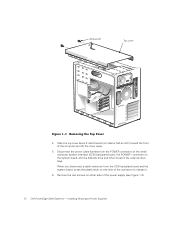
... the cover away. 5. When you disconnect a cable connector from the POWER connector on the small computer system interface (SCSI) backplane board, the POWER1 connector on either side of the power supply (see Figure 1-2). 1-2 Dell PowerEdge 2400 Systems - Slide the top cover about 2 centimeters (cm) (about half an inch) toward the front of the connector...
... the cover away. 5. When you disconnect a cable connector from the POWER connector on the small computer system interface (SCSI) backplane board, the POWER1 connector on either side of the power supply (see Figure 1-2). 1-2 Dell PowerEdge 2400 Systems - Slide the top cover about 2 centimeters (cm) (about half an inch) toward the front of the connector...
Installing Redundant Power Supplies
Page 7
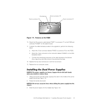
... the handle downward. 3. Using your thumb and index finger, squeeze the catch in the middle of the power supply handle (see Figure 1-3). Dell PowerEdge 2400 Systems - c. Replace the two computer covers. 1. Installing Redundant Power Supplies 1-5 Attach the 18-pin connector labeled "PWR2" to the diskette ...perform the following steps: a. Attach the 16-pin connector to connector P1 on the PSDB and connector POWER1 on the SCSI backplane board. Thumbscrew Power connector P2 Power connector P3 Power Connector P1 10. To attach the cable harness provided in the external ...
... the handle downward. 3. Using your thumb and index finger, squeeze the catch in the middle of the power supply handle (see Figure 1-3). Dell PowerEdge 2400 Systems - c. Replace the two computer covers. 1. Installing Redundant Power Supplies 1-5 Attach the 18-pin connector labeled "PWR2" to the diskette ...perform the following steps: a. Attach the 16-pin connector to connector P1 on the PSDB and connector POWER1 on the SCSI backplane board. Thumbscrew Power connector P2 Power connector P3 Power Connector P1 10. To attach the cable harness provided in the external ...


