
Information Update
Page 5
...Intel® dual-port Gb Ethernet network adapter daughter card. See support.dell.com for information on the optional Intel Gb Ethernet daughter card can be teamed using BASP. NIC Teaming Restrictions Each server module (blade) in your system provides... network teaming support under the following topics: • Quad-core processor upgrades • NIC teaming restrictions • Fibre Channel pass-through module...
...Intel® dual-port Gb Ethernet network adapter daughter card. See support.dell.com for information on the optional Intel Gb Ethernet daughter card can be teamed using BASP. NIC Teaming Restrictions Each server module (blade) in your system provides... network teaming support under the following topics: • Quad-core processor upgrades • NIC teaming restrictions • Fibre Channel pass-through module...
Configuration Guide
Page 5
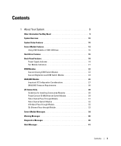
... or Telnet Console 17 Redirecting the DRAC/MC Serial Console to the Ethernet Switch Module 19 Updating the DRAC/MC Module Firmware 19 Integrating the System Into the Network 22 Updating the PowerConnect Switch Module Firmware 27 Configuring the Cisco Catalyst Blade Switch 3030 29 Configuring the ... Using a Web Browser and a Management Station 29 Configuring the SwItch Using a Serial or Telnet Console 30 Gb Pass-through Module 31 Gb Pass-through Module Link Negotiations 31 Enabling PXE on a Gb Ethernet Daughter Card 31 Enabling PXE on the Broadcom TOE NIC Daughter Card 31 Contents 3
... or Telnet Console 17 Redirecting the DRAC/MC Serial Console to the Ethernet Switch Module 19 Updating the DRAC/MC Module Firmware 19 Integrating the System Into the Network 22 Updating the PowerConnect Switch Module Firmware 27 Configuring the Cisco Catalyst Blade Switch 3030 29 Configuring the ... Using a Web Browser and a Management Station 29 Configuring the SwItch Using a Serial or Telnet Console 30 Gb Pass-through Module 31 Gb Pass-through Module Link Negotiations 31 Enabling PXE on a Gb Ethernet Daughter Card 31 Enabling PXE on the Broadcom TOE NIC Daughter Card 31 Contents 3

Configuration Guide
Page 8
... 4 5 6 3 7 2 1 8 1 I/O bay 2 4 I/O bay 1 7 KVM module 10 blanks (2) 9 2 fan modules (2) 5 Fibre Channel pass-through module 8 DRAC/MC module 11 I/O bay 4 3 Ethernet switch module 6 I/O bay 3 9 power supply modules (4) 12 blanks (2) Other Documents You May Need The Product Information Guide provides important safety and regulatory ... system components. • The Dell Remote Access Controller/Modular Chassis User's Guide provides detailed information on using the remote management features of the system. • The Dell PowerEdge Expandable RAID Controller 5iR Integrated Mirroring...
... 4 5 6 3 7 2 1 8 1 I/O bay 2 4 I/O bay 1 7 KVM module 10 blanks (2) 9 2 fan modules (2) 5 Fibre Channel pass-through module 8 DRAC/MC module 11 I/O bay 4 3 Ethernet switch module 6 I/O bay 3 9 power supply modules (4) 12 blanks (2) Other Documents You May Need The Product Information Guide provides important safety and regulatory ... system components. • The Dell Remote Access Controller/Modular Chassis User's Guide provides detailed information on using the remote management features of the system. • The Dell PowerEdge Expandable RAID Controller 5iR Integrated Mirroring...

Configuration Guide
Page 28
...as 192.168.1.123 (example only) and subnet mask of the default gateway To configure the PowerConnect 5316M Ethernet switch module using the internal serial port on the chassis. The Gb Ethernet pass-through the DRAC/MC console, enter the following command: connect switch-x where x is also available as...(10 Mb and 100 Mb ports are user-selectable. 5 Configure the static address to the VLAN 1 interface through module is the module slot number on the DRAC/MC module, perform the following commands: console(config-if)# exit console(config)# ip default-gateway 192.168.1.1 26 General System ...
...as 192.168.1.123 (example only) and subnet mask of the default gateway To configure the PowerConnect 5316M Ethernet switch module using the internal serial port on the chassis. The Gb Ethernet pass-through the DRAC/MC console, enter the following command: connect switch-x where x is also available as...(10 Mb and 100 Mb ports are user-selectable. 5 Configure the static address to the VLAN 1 interface through module is the module slot number on the DRAC/MC module, perform the following commands: console(config-if)# exit console(config)# ip default-gateway 192.168.1.1 26 General System ...
Configuration Guide
Page 33
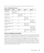
.... Enabling PXE on a Gb Ethernet Daughter Card To enable PXE on support.dell.com. NOTE: If PXE is enabled, the default connection is port LOM 1. Enabling PXE on the external switch (10 Mb and 100 Mb ports are not supported). Gb Pass-through Module Gb Pass-through Module Link Negotiations A Gb pass-through module. For more information, see...
.... Enabling PXE on a Gb Ethernet Daughter Card To enable PXE on support.dell.com. NOTE: If PXE is enabled, the default connection is port LOM 1. Enabling PXE on the external switch (10 Mb and 100 Mb ports are not supported). Gb Pass-through Module Gb Pass-through Module Link Negotiations A Gb pass-through module. For more information, see...
Getting Started Guide
Page 17
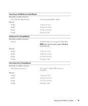
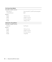
... accessible connectors Gb 10/100/1000 Mbps Ethernet Physical Height Width Depth Weight Gb Ethernet Pass-Through Module Externally accessible connectors Ethernet Physical Height Width Depth Weight Fibre Channel Pass-Through Module Externally accessible connectors Fibre Channel transceiver Physical Height Width Depth Weight Six autonegotiating RJ-45 uplinks 3.302 cm (1.3 in) 13.081 cm (5.15 in) 27...
... accessible connectors Gb 10/100/1000 Mbps Ethernet Physical Height Width Depth Weight Gb Ethernet Pass-Through Module Externally accessible connectors Ethernet Physical Height Width Depth Weight Fibre Channel Pass-Through Module Externally accessible connectors Fibre Channel transceiver Physical Height Width Depth Weight Six autonegotiating RJ-45 uplinks 3.302 cm (1.3 in) 13.081 cm (5.15 in) 27...
Getting Started Guide
Page 18
Fibre Channel Switch Module Externally accessible connectors Fibre Channel 1/2/4 Gb/s Ethernet Physical Height Width Depth Weight Infiniband Pass-Through Module Externally accessible connectors Infiniband Physical Height Width Depth Weight Four universal (E, F, and FL) autosensing ports RJ-45 3.302 cm (1.3 in) 13.081 cm (5.15 in) 27.432 cm (10.8 in) 1.06 kg (2.35 lb) Ten 4X ports 3.302 cm (1.3 in) 13.081 cm (5.15 in) 27.432 cm (10.8 in) 1.8 kg (4 lb) 16 Getting Started With Your System
Fibre Channel Switch Module Externally accessible connectors Fibre Channel 1/2/4 Gb/s Ethernet Physical Height Width Depth Weight Infiniband Pass-Through Module Externally accessible connectors Infiniband Physical Height Width Depth Weight Four universal (E, F, and FL) autosensing ports RJ-45 3.302 cm (1.3 in) 13.081 cm (5.15 in) 27.432 cm (10.8 in) 1.06 kg (2.35 lb) Ten 4X ports 3.302 cm (1.3 in) 13.081 cm (5.15 in) 27.432 cm (10.8 in) 1.8 kg (4 lb) 16 Getting Started With Your System
Hardware Owner's Manual (PDF)
Page 3
... Avocent Digital Access KVM Switch Module 24 DRAC/MC Module 26 Important I/O Configuration Considerations 27 DRAC/MC Firmware Requirements 28 I/O Connectivity 28 Guidelines for Installing Connectivity Modules 28 PowerConnect 5316M Ethernet Switch Module 29 Fibre Channel Pass-Through Module 31 Fibre Channel Switch Module 32 Infiniband Pass-through Module 32 Gb Ethernet Pass-through Module 33 Server Module Messages 34 Warning Messages 40 Diagnostics...
... Avocent Digital Access KVM Switch Module 24 DRAC/MC Module 26 Important I/O Configuration Considerations 27 DRAC/MC Firmware Requirements 28 I/O Connectivity 28 Guidelines for Installing Connectivity Modules 28 PowerConnect 5316M Ethernet Switch Module 29 Fibre Channel Pass-Through Module 31 Fibre Channel Switch Module 32 Infiniband Pass-through Module 32 Gb Ethernet Pass-through Module 33 Server Module Messages 34 Warning Messages 40 Diagnostics...
Hardware Owner's Manual (PDF)
Page 16
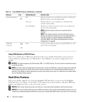
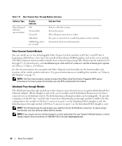
...custom cable to connect external USB devices and video to configure the server module. NOTICE: The system supports only Dell-branded USB 1.1 or USB 2.0 drives. Hard-Drive Features Each server module supports one or two hot-pluggable SAS hard drives, or one or two... to the server module. Table 1-2. See Figure 1-4 and Table 1-3 for a diskette drive or USB CD drive. Server Module Features and Indicators (continued) Indicator Icon Network indicators Activity Indicator Off Indicator Code Indicates that the server module has a valid link to the Ethernet switch or pass-through module.
...custom cable to connect external USB devices and video to configure the server module. NOTICE: The system supports only Dell-branded USB 1.1 or USB 2.0 drives. Hard-Drive Features Each server module supports one or two hot-pluggable SAS hard drives, or one or two... to the server module. Table 1-2. See Figure 1-4 and Table 1-3 for a diskette drive or USB CD drive. Server Module Features and Indicators (continued) Indicator Icon Network indicators Activity Indicator Off Indicator Code Indicates that the server module has a valid link to the Ethernet switch or pass-through module.

Hardware Owner's Manual (PDF)
Page 18
... and the numbering for the bays. Figure 1-5. Back-Panel Features 1 2 3 4 12 11 5 6 4 3 10 1 I/O bay 2 4 I/O bay 1 7 KVM module 10 blanks (2) 7 2 1 8 9 2 fan modules (2) 5 Fibre Channel pass-through module 8 DRAC/MC module 11 I/O bay 4 3 PowerConnect 5316M Ethernet switch module 6 I /O module bays, the DRAC/MC, fan modules, and power supply modules. Back-Panel Features The back of the chassis supports four I /O bay 3 9 power supply...
... and the numbering for the bays. Figure 1-5. Back-Panel Features 1 2 3 4 12 11 5 6 4 3 10 1 I/O bay 2 4 I/O bay 1 7 KVM module 10 blanks (2) 7 2 1 8 9 2 fan modules (2) 5 Fibre Channel pass-through module 8 DRAC/MC module 11 I/O bay 4 3 PowerConnect 5316M Ethernet switch module 6 I /O module bays, the DRAC/MC, fan modules, and power supply modules. Back-Panel Features The back of the chassis supports four I /O bay 3 9 power supply...
Hardware Owner's Manual (PDF)
Page 19
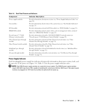
... page 20). Back-Panel Features and Indicators Component Power supply modules Fan modules KVM module DRAC/MC module PowerConnect™ 5316M Ethernet switch module Fibre Channel pass-through module Fibre Channel switch module Infiniband pass-through module Gb pass-through Module" on page 29). Provides information about the network status (see "Gb Ethernet Pass-through module Indicator Description Provide information about power status, fault, and the...
... page 20). Back-Panel Features and Indicators Component Power supply modules Fan modules KVM module DRAC/MC module PowerConnect™ 5316M Ethernet switch module Fibre Channel pass-through module Fibre Channel switch module Infiniband pass-through module Gb pass-through Module" on page 29). Provides information about the network status (see "Gb Ethernet Pass-through module Indicator Description Provide information about power status, fault, and the...
Hardware Owner's Manual (PDF)
Page 29
... installed in bays I/O 1 and I /O 1 bay. Table 1-9 lists the valid I /O bays 3 and 4 require that you install a Gb Ethernet daughter card in the server module. through module N/A Fibre channel switch or pass- Table 1-10 lists the indicators on the server module and operate at 1/2/4 Gb. If redundancy is a 16-port switch with 6 uplinks and 10 downlinks (see...
... installed in bays I/O 1 and I /O 1 bay. Table 1-9 lists the valid I /O bays 3 and 4 require that you install a Gb Ethernet daughter card in the server module. through module N/A Fibre channel switch or pass- Table 1-10 lists the indicators on the server module and operate at 1/2/4 Gb. If redundancy is a 16-port switch with 6 uplinks and 10 downlinks (see...
Hardware Owner's Manual (PDF)
Page 32
..., use only SFPs provided with I /O bay 3 connects to port 1 on the Infiniband HCA daughter card. Fibre Channel Pass-Through Module Indicators Indicator Type Fibre Channel indicator (green/amber) Activity Indicator Off Green/amber Green/off to a valid link partner on page... The Infiniband pass-through module in the server module and 4x Infiniband Transceivers for the functionality and location of the switch module indicators. the Infiniband pass-through modules are hot-pluggable. Fibre Channel Switch Module You can install one Ethernet port with the module. Table 1-11...
..., use only SFPs provided with I /O bay 3 connects to port 1 on the Infiniband HCA daughter card. Fibre Channel Pass-Through Module Indicators Indicator Type Fibre Channel indicator (green/amber) Activity Indicator Off Green/amber Green/off to a valid link partner on page... The Infiniband pass-through module in the server module and 4x Infiniband Transceivers for the functionality and location of the switch module indicators. the Infiniband pass-through modules are hot-pluggable. Fibre Channel Switch Module You can install one Ethernet port with the module. Table 1-11...
Hardware Owner's Manual (PDF)
Page 33
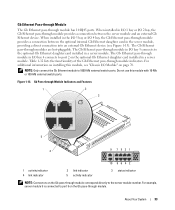
When installed in the I/O 3 bay or I /O Module" on the Gb pass-through module correspond directly to the server module number. The Gb Ethernet pass-through module provides a connection between the server module and an external Gb Ethernet device. Gb Ethernet Pass-through Module The Gb Ethernet pass-through module indicators. Table 1-12 lists the functionality of the Gb Ethernet pass-through module has 10 RJ45 ports. For additional information...
When installed in the I/O 3 bay or I /O Module" on the Gb pass-through module correspond directly to the server module number. The Gb Ethernet pass-through module provides a connection between the server module and an external Gb Ethernet device. Gb Ethernet Pass-through Module The Gb Ethernet pass-through module indicators. Table 1-12 lists the functionality of the Gb Ethernet pass-through module has 10 RJ45 ports. For additional information...

Hardware Owner's Manual (PDF)
Page 34
... System messages appear on page 28. Damage due to the server module and there is no network activity. CAUTION: Many repairs may only be done by your product documentation, or as directed by Dell is running when the message appears or the operating system's documentation... you of the message and recommended action. 34 About Your System Gb Pass-through Module Indicators Indicator Type Activity Indicator Indicator Code Link Green/amber indicator/activity blinking indicator Green/off The Gb Ethernet connector is not linked to servicing that is not authorized by the online...
... System messages appear on page 28. Damage due to the server module and there is no network activity. CAUTION: Many repairs may only be done by your product documentation, or as directed by Dell is running when the message appears or the operating system's documentation... you of the message and recommended action. 34 About Your System Gb Pass-through Module Indicators Indicator Type Activity Indicator Indicator Code Link Green/amber indicator/activity blinking indicator Green/off The Gb Ethernet connector is not linked to servicing that is not authorized by the online...

Hardware Owner's Manual (PDF)
Page 70
...The completion dialog box appears. 7 Click Finish to exit. 8 Start up to replace an I /O modules, such as Fibre Channel pass-through, Fiber Channel switch, Ethernet passthrough, Infiniband pass-through the Remote Console Switch software. however, your system. You do not have to turn off the ...system to four hot-pluggable I /O module. To include unpowered SIPs in the appliance, a completion dialog ...
...The completion dialog box appears. 7 Click Finish to exit. 8 Start up to replace an I /O modules, such as Fibre Channel pass-through, Fiber Channel switch, Ethernet passthrough, Infiniband pass-through the Remote Console Switch software. however, your system. You do not have to turn off the ...system to four hot-pluggable I /O module. To include unpowered SIPs in the appliance, a completion dialog ...

Hardware Owner's Manual (PDF)
Page 71
.../3 and IO/4. Installing System Options 71 NOTICE: You must be installed in either bay IO/1 or IO/2. PowerConnect 5316M Ethernet switch modules or Ethernet pass-through modules must install a filler bracket over the empty slot opening. I/O Module Placements The back panel has four bays for guidelines on page 83. Bays IO/1 and IO/3 are primary bays...
.../3 and IO/4. Installing System Options 71 NOTICE: You must be installed in either bay IO/1 or IO/2. PowerConnect 5316M Ethernet switch modules or Ethernet pass-through modules must install a filler bracket over the empty slot opening. I/O Module Placements The back panel has four bays for guidelines on page 83. Bays IO/1 and IO/3 are primary bays...

Hardware Owner's Manual (PDF)
Page 72
... 5 must be installed in bay IO/1. Removing and Installing an I/O Module 1 2 1 I/O module 2 release lever Installing an I/O Module 1 Unpack the I /O module. b Slide the module into place. 3 If a daughter card(s) was included with the Fibre Channel pass-through module for a second PowerConnect 5316M Ethernet switch module or Gb Ethernet pass-through module connector number 5 (primary and secondary bays). 72 Installing System Options Bay IO...
... 5 must be installed in bay IO/1. Removing and Installing an I/O Module 1 2 1 I/O module 2 release lever Installing an I/O Module 1 Unpack the I /O module. b Slide the module into place. 3 If a daughter card(s) was included with the Fibre Channel pass-through module for a second PowerConnect 5316M Ethernet switch module or Gb Ethernet pass-through module connector number 5 (primary and secondary bays). 72 Installing System Options Bay IO...
Hardware Owner's Manual (PDF)
Page 157
...123 drive carrier SATA hard drive (SATA), 91 D damaged systems troubleshooting, 107 daughter card installing, 82 status indicator, 15 Dell contacting, 132 diagnostics advanced testing options, 119 error messages, 120 running from the utility partition, 118 see system diagnostics and ... Avocent Analog KVM switch module, 22 Avocent Digital Access KVM switch module, 24 back-panel, 18 DRAC/MC module, 26 Fibre Channel pass-through module, 31 Fibre Channel switch module, 32 Gb Ethernet pass-through module, 33 hard drive, 16 I/O connectivity, 27-28 Infiniband pass-through module, 32 KVM selection, 15...
...123 drive carrier SATA hard drive (SATA), 91 D damaged systems troubleshooting, 107 daughter card installing, 82 status indicator, 15 Dell contacting, 132 diagnostics advanced testing options, 119 error messages, 120 running from the utility partition, 118 see system diagnostics and ... Avocent Analog KVM switch module, 22 Avocent Digital Access KVM switch module, 24 back-panel, 18 DRAC/MC module, 26 Fibre Channel pass-through module, 31 Fibre Channel switch module, 32 Gb Ethernet pass-through module, 33 hard drive, 16 I/O connectivity, 27-28 Infiniband pass-through module, 32 KVM selection, 15...

Hardware Owner's Manual (PDF)
Page 158
... button, 14 system, 10 system control panel, 11 system identification, 11 system status, 10 Fibre Channel pass-through module, 31 Fibre Channel switch module, 32 G Gb Ethernet pass-through module, 33 getting help, 127 guidelines memory installation, 78 H hard drive installing SATA in a SATA drive carrier, 91 removing from a drive carrier, 91 hard drives, 89 ...
... button, 14 system, 10 system control panel, 11 system identification, 11 system status, 10 Fibre Channel pass-through module, 31 Fibre Channel switch module, 32 G Gb Ethernet pass-through module, 33 getting help, 127 guidelines memory installation, 78 H hard drive installing SATA in a SATA drive carrier, 91 removing from a drive carrier, 91 hard drives, 89 ...

