
Information Update
Page 3
... Features 5 New High-Efficiency Power Supply and Power Monitoring Features 5 New I/O and Storage Features 6 New Security Features 6 Optional Internal USB Memory Key 6 Installing the Optional Internal USB Memory Key . . 8 Support for 8-GB Memory Modules - PowerEdge 1950 III Systems 9 Processor Upgrades - Safeguarding Encrypted Data 10 System Message Update 10 LCD Status Messages Update 15 Contents 3
... Features 5 New High-Efficiency Power Supply and Power Monitoring Features 5 New I/O and Storage Features 6 New Security Features 6 Optional Internal USB Memory Key 6 Installing the Optional Internal USB Memory Key . . 8 Support for 8-GB Memory Modules - PowerEdge 1950 III Systems 9 Processor Upgrades - Safeguarding Encrypted Data 10 System Message Update 10 LCD Status Messages Update 15 Contents 3
Information Update
Page 6
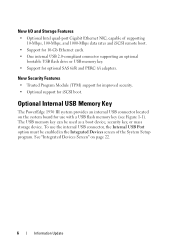
...Figure 1-1). Optional Internal USB Memory Key The PowerEdge 1950 III system provides an internal USB connector located on page 22. 6 Information Update New I/O and Storage Features • Optional Intel quad-port Gigabit Ethernet NIC, capable of the System Setup program. The USB memory key can be... • Support for 10-Gb Ethernet cards. • One internal USB 2.0-compliant connector supporting an optional bootable USB flash drive or USB memory key. • Support for use the internal USB connector, the Internal USB Port option must be used as a boot device, security key, or...
...Figure 1-1). Optional Internal USB Memory Key The PowerEdge 1950 III system provides an internal USB connector located on page 22. 6 Information Update New I/O and Storage Features • Optional Intel quad-port Gigabit Ethernet NIC, capable of the System Setup program. The USB memory key can be... • Support for 10-Gb Ethernet cards. • One internal USB 2.0-compliant connector supporting an optional bootable USB flash drive or USB memory key. • Support for use the internal USB connector, the Internal USB Port option must be used as a boot device, security key, or...
Information Update
Page 7
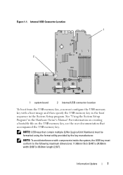
... the system, the USB key must configure the USB memory key with a boot image and then specify the USB memory key in the boot sequence in the Hardware Owner's Manual. Internal USB Connector Location 1 2 1 system board 2 internal USB connector location To boot from the USB memory key, you...width (0.98") x 66.8mm length (2.63"). NOTE: USB keys that accompanied the USB memory key. See "Using the System Setup Program" in the System Setup program. Information Update 7 For information on creating a bootable file on the USB memory key, see the user documentation that contain multiple LUNs ...
... the system, the USB key must configure the USB memory key with a boot image and then specify the USB memory key in the boot sequence in the Hardware Owner's Manual. Internal USB Connector Location 1 2 1 system board 2 internal USB connector location To boot from the USB memory key, you...width (0.98") x 66.8mm length (2.63"). NOTE: USB keys that accompanied the USB memory key. See "Using the System Setup Program" in the System Setup program. Information Update 7 For information on creating a bootable file on the USB memory key, see the user documentation that contain multiple LUNs ...
Information Update
Page 8
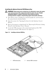
..., working inside the computer, and protecting against electrostatic discharge. 1 Turn off the system, including any of the components inside the system. Installing the Optional Internal USB Memory Key WARNING: Only trained service technicians are authorized to remove the system cover and access any attached peripherals, and disconnect the system from its...
..., working inside the computer, and protecting against electrostatic discharge. 1 Turn off the system, including any of the components inside the system. Installing the Optional Internal USB Memory Key WARNING: Only trained service technicians are authorized to remove the system cover and access any attached peripherals, and disconnect the system from its...
Information Update
Page 9
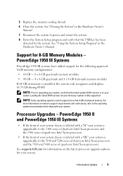
... the Hardware Owner's Manual. Support for information on memory support requirements and restrictions, refer to upgrading your system, verify that the USB key has been detected by the system. Loading the latest BIOS version ensures that ships with a "III," your system is labeled... x 8-GB quad-rank and 4 x 4-GB dual-rank memory modules If 64 GB of physical memory. See support.dell.com for 8-GB Memory Modules - PowerEdge 1950 II and PowerEdge 1950 III Systems • If the front of your system chassis is fully supported. NOTE: Prior to the operating system documentation...
... the Hardware Owner's Manual. Support for information on memory support requirements and restrictions, refer to upgrading your system, verify that the USB key has been detected by the system. Loading the latest BIOS version ensures that ships with a "III," your system is labeled... x 8-GB quad-rank and 4 x 4-GB dual-rank memory modules If 64 GB of physical memory. See support.dell.com for 8-GB Memory Modules - PowerEdge 1950 II and PowerEdge 1950 III Systems • If the front of your system chassis is fully supported. NOTE: Prior to the operating system documentation...
Information Update
Page 11
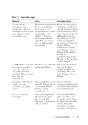
...boot device available Faulty or missing optical drive subsystem, hard drive, or hard-drive subsystem, or no bootable USB key installed. See "Installing a RAC Card" in the Hardware Owner's Manual. !!*** Error: Remote Access Controller initialization failure *** RAC virtual... example, a failed other system messages for DIMM) so that supports configuration has changed node interleaving. controller slot. Use a bootable USB key, CD, or hard drive. Table 1-1. System Messages Message Causes Corrective Actions Alert! Memory configuration does not support Node Interleaving. Information Update ...
...boot device available Faulty or missing optical drive subsystem, hard drive, or hard-drive subsystem, or no bootable USB key installed. See "Installing a RAC Card" in the Hardware Owner's Manual. !!*** Error: Remote Access Controller initialization failure *** RAC virtual... example, a failed other system messages for DIMM) so that supports configuration has changed node interleaving. controller slot. Use a bootable USB key, CD, or hard drive. Table 1-1. System Messages Message Causes Corrective Actions Alert! Memory configuration does not support Node Interleaving. Information Update ...
Information Update
Page 15
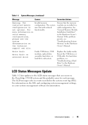
... persists, see "Troubleshooting a Hard Drive" in the system event log (SEL). Reseat the USB device or USB cable. Invalid memory configuration. Ensure that can occur on selected drive Faulty USB device, USB medium, optical drive assembly, hard drive, or hard-drive subsystem. Replace the faulty media. ...Warning: The installed memory configuration is not optimal. The system runs but with reduced functionality. Write fault Write fault on the PowerEdge 1950 III system and the probable cause for each message. The LCD messages refer to the LCD status messages that the memory modules ...
... persists, see "Troubleshooting a Hard Drive" in the system event log (SEL). Reseat the USB device or USB cable. Invalid memory configuration. Ensure that can occur on selected drive Faulty USB device, USB medium, optical drive assembly, hard drive, or hard-drive subsystem. Replace the faulty media. ...Warning: The installed memory configuration is not optimal. The system runs but with reduced functionality. Write fault Write fault on the PowerEdge 1950 III system and the probable cause for each message. The LCD messages refer to the LCD status messages that the memory modules ...
Information Update
Page 19
... Device plugged in the Hardware Owner's Manual. Reseat the device cable. See "Expansion Card Risers" in the specified USB port caused an overcurrent condition. If the problem persists, the riser card or system board is missing or disconnected. See "Installing a RAC Card" in the ...
... Device plugged in the Hardware Owner's Manual. Reseat the device cable. See "Expansion Card Risers" in the specified USB port caused an overcurrent condition. If the problem persists, the riser card or system board is missing or disconnected. See "Installing a RAC Card" in the ...

Information Update
Page 22
... the operating system is automatically set to initialize the timer. NOTE: You can only enable the internal USB port if the User Accessible USB Ports option on this feature. when disabled, the CPU Performance State tables are reported to the operating ...specification. Table 1-5. Enables or disables demand-based power management. Integrated Devices Screen Options Option Description Internal USB Port (On default) Enables or disables the system's internal USB port. CPU Information Screen Option Demand-Based Power Management (Enabled default) Description NOTE: Check your ...
... the operating system is automatically set to initialize the timer. NOTE: You can only enable the internal USB port if the User Accessible USB Ports option on this feature. when disabled, the CPU Performance State tables are reported to the operating ...specification. Table 1-5. Enables or disables demand-based power management. Integrated Devices Screen Options Option Description Internal USB Port (On default) Enables or disables the system's internal USB port. CPU Information Screen Option Demand-Based Power Management (Enabled default) Description NOTE: Check your ...

Information Update
Page 26
You cannot save the file to specify the diskette drive or USB memory key where the test log file is saved. System Diagnostics Custom Test Options In the Customize window of the system diagnostics, the Log output file pathname option enables you to a hard drive. 26 Information Update Hardware Owner's Manual Updates Installing the Processor When installing the processor, the processor shield must be closed before securing the processor with the socket release lever.
You cannot save the file to specify the diskette drive or USB memory key where the test log file is saved. System Diagnostics Custom Test Options In the Customize window of the system diagnostics, the Log output file pathname option enables you to a hard drive. 26 Information Update Hardware Owner's Manual Updates Installing the Processor When installing the processor, the processor shield must be closed before securing the processor with the socket release lever.
Information Update
Page 31
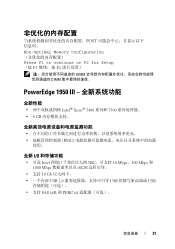
POST Non-Optimal Memory Configuration Press F1 to continue or F2 for Setup (按 F1 F2 DIMM DIMM PowerEdge 1950 III 全新性能 Intel® Xeon® 5400 系列和 5300 8 GB BMC 使用。 全新 I/O • 可选 Intel NIC 10 Mbps、100 Mbps 和 1000 Mbps iSCSI • 支持 10 Gb USB 2.0 USB USB SAS 6i/R 和 PERC 6/i 信息更新 31
POST Non-Optimal Memory Configuration Press F1 to continue or F2 for Setup (按 F1 F2 DIMM DIMM PowerEdge 1950 III 全新性能 Intel® Xeon® 5400 系列和 5300 8 GB BMC 使用。 全新 I/O • 可选 Intel NIC 10 Mbps、100 Mbps 和 1000 Mbps iSCSI • 支持 10 Gb USB 2.0 USB USB SAS 6i/R 和 PERC 6/i 信息更新 31

Information Update
Page 36
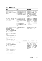
... 失败。 initialization failure *** RAC virtual USB devices may not be available RAC 虚拟 USB RAC 卡"。 Invalid PCIe card found in the Internal_Storage slot! (在 Internal_Storage PCIe 卡!) PCIe PCIe SAS 36 信息更新 表 1-1 列出 PowerEdge 1950 III 表 1-1 信息 原因...
... 失败。 initialization failure *** RAC virtual USB devices may not be available RAC 虚拟 USB RAC 卡"。 Invalid PCIe card found in the Internal_Storage slot! (在 Internal_Storage PCIe 卡!) PCIe PCIe SAS 36 信息更新 表 1-1 列出 PowerEdge 1950 III 表 1-1 信息 原因...
Information Update
Page 37
表 1-1 信息 原因 纠正措施 No boot device USB 钥匙、 available CD 导设备) USB PCI BIOS failed to install PCI BIOS) 在 shadowing PCIe 设备 BIOS(选项 ROM PCIe Degraded Link Width Error: 故障&#...
表 1-1 信息 原因 纠正措施 No boot device USB 钥匙、 available CD 导设备) USB PCI BIOS failed to install PCI BIOS) 在 shadowing PCIe 设备 BIOS(选项 ROM PCIe Degraded Link Width Error: 故障&#...
Information Update
Page 40
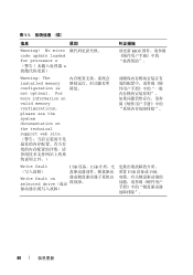
For more information on valid memory configurations, please see the system documentation on the technical support web site Write fault USB 设备、USB Write fault on selected drive USB 设备或 USB 40 信息更新 No micro code update loaded for processor n n 请更新 BIOS Warning: The installed memory configuration is not optimal. 表 1-1 信息 原因 纠正措施 Warning!
For more information on valid memory configurations, please see the system documentation on the technical support web site Write fault USB 设备、USB Write fault on selected drive USB 设备或 USB 40 信息更新 No micro code update loaded for processor n n 请更新 BIOS Warning: The installed memory configuration is not optimal. 表 1-1 信息 原因 纠正措施 Warning!

Information Update
Page 43
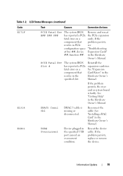
LCD 代码 E171F E1914 E1B01 E2110 文本 原因 纠正措施 PCIE Fatal Err B## D## F## 系统 BIOS PCIe PCIe PCIe PCIE Fatal Err Slot # 系统 BIOS PCIe 升板"。 DRAC5 Conn2 Cbl DRAC 5 RAC 卡"。 USB# Overcurrent USB 流条件。 下设备。 MBE DIMM DIMM MBE 信息更新 43 表 1-2.
LCD 代码 E171F E1914 E1B01 E2110 文本 原因 纠正措施 PCIE Fatal Err B## D## F## 系统 BIOS PCIe PCIe PCIe PCIE Fatal Err Slot # 系统 BIOS PCIe 升板"。 DRAC5 Conn2 Cbl DRAC 5 RAC 卡"。 USB# Overcurrent USB 流条件。 下设备。 MBE DIMM DIMM MBE 信息更新 43 表 1-2.
Information Update
Page 46
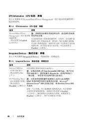
... CPU CPU CPU Disabled Integrated Devices 表 1-5 Integrated Devices 表 1-5. Integrated Devices 选项 说明 Internal USB Port (内部 USB On [ 开 ]) USB 端口。 User Accessible USB Ports USB All ports On USB 端口。 OS Watchdog Timer ACPI) 3.0b 规格的 (OS WDAT Microsoft® Windows...
... CPU CPU CPU Disabled Integrated Devices 表 1-5 Integrated Devices 表 1-5. Integrated Devices 选项 说明 Internal USB Port (内部 USB On [ 开 ]) USB 端口。 User Accessible USB Ports USB All ports On USB 端口。 OS Watchdog Timer ACPI) 3.0b 规格的 (OS WDAT Microsoft® Windows...
Information Update
Page 126
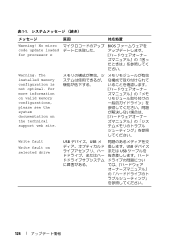
表 1-1 原因 対応処置 Warning! No micro code update loaded for processor n BIOS ださい。 Warning: The installed memory configuration is not optimal. For more information on valid memory configurations, please see the system documentation on selected drive USB USB USB USB 126 Write fault Write fault on the technical support web site.
表 1-1 原因 対応処置 Warning! No micro code update loaded for processor n BIOS ださい。 Warning: The installed memory configuration is not optimal. For more information on valid memory configurations, please see the system documentation on selected drive USB USB USB USB 126 Write fault Write fault on the technical support web site.

Information Update
Page 133
Integrated Devices 説明 Internal USB Port USB On) USB User Accessible USB Ports USB ポ All ports On(すべて きます。 133 CPU Information(CPU Demand-Based Power Management Enabled) 説明 メモ:OS CPU OS CPU OS CPU が 1 Disabled Integrated Devices Integrated Devices 1-5 表 1-5. CPU Information(CPU Demand-Based Power Management 1-4 表 1-4.
Integrated Devices 説明 Internal USB Port USB On) USB User Accessible USB Ports USB ポ All ports On(すべて きます。 133 CPU Information(CPU Demand-Based Power Management Enabled) 説明 メモ:OS CPU OS CPU OS CPU が 1 Disabled Integrated Devices Integrated Devices 1-5 表 1-5. CPU Information(CPU Demand-Based Power Management 1-4 表 1-4.
Information Update
Page 149
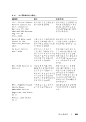
... Setup 십시오. 표 1-1 메시지 원인 !!*** Error: Remote Access Controller initialization failure *** RAC virtual USB devices may not be available... RAC Invalid PCIe card found in the Internal_Storage slot! PCI BIOS failed to install PCIe BIOS(옵션 ROM PCIe ...
... Setup 십시오. 표 1-1 메시지 원인 !!*** Error: Remote Access Controller initialization failure *** RAC virtual USB devices may not be available... RAC Invalid PCIe card found in the Internal_Storage slot! PCI BIOS failed to install PCIe BIOS(옵션 ROM PCIe ...
Information Update
Page 152
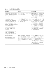
표 1-1 메시지 원인 Warning! For more information on valid memory configurations, please see the system documentation on selected drive USB 장치, USB USB USB 케 니다. 152 Write fault Write fault on the technical support web site. No micro code update loaded for processor n BIOS Warning: The installed memory configuration is not optimal.
표 1-1 메시지 원인 Warning! For more information on valid memory configurations, please see the system documentation on selected drive USB 장치, USB USB USB 케 니다. 152 Write fault Write fault on the technical support web site. No micro code update loaded for processor n BIOS Warning: The installed memory configuration is not optimal.


