

Installing a SATA Optical Drive
Page 6
.... b Bend the cable toward the chipset shroud and insert the cable into position. 2 Connect the SATA cable (the end with a cable provided in a PowerEdge 1950 Drive Tray 2 3 1 4 5 1 optical drive 3 SATA power cable 5 optical drive carrier 2 SATA cable 4 carrier latch Installing the SATA Optical Drive - PowerEdge 1950 1 Insert the optical drive tray into the system until it is fully inserted and...
.... b Bend the cable toward the chipset shroud and insert the cable into position. 2 Connect the SATA cable (the end with a cable provided in a PowerEdge 1950 Drive Tray 2 3 1 4 5 1 optical drive 3 SATA power cable 5 optical drive carrier 2 SATA cable 4 carrier latch Installing the SATA Optical Drive - PowerEdge 1950 1 Insert the optical drive tray into the system until it is fully inserted and...

Installing a SATA Optical Drive
Page 7
... connector. See "Closing the System" in the PowerEdge 1950 2 1 3 4 6 5 1 SATA data cable 3 chipset shroud 5 SATA power cable 2 SATA_A connector on the system and attached peripherals. Installing a SATA Optical Drive 7 PowerEdge 2970 or 2950 1 Insert the optical drive tray into the system until it is fully inserted and locked into position. 2 Connect the SATA cable (the end with the branching...
... connector. See "Closing the System" in the PowerEdge 1950 2 1 3 4 6 5 1 SATA data cable 3 chipset shroud 5 SATA power cable 2 SATA_A connector on the system and attached peripherals. Installing a SATA Optical Drive 7 PowerEdge 2970 or 2950 1 Insert the optical drive tray into the system until it is fully inserted and locked into position. 2 Connect the SATA cable (the end with the branching...

Installing a SATA Optical Drive
Page 8
...until the bracket detaches from the chassis slots. 6 Route the SATA cable in the cable channel in the PowerEdge 2950 and 2970 1 2 3 4 5 1 SATA_B connector on the system board. See Figure 1-4. 7 Route the SATA cable along the top of the chassis and replace the cable ... 1-4. SATA Cable Routing in the right wall of the cable retention bracket to the central riser. 8 Bend the cable behind the central riser and connect the cable to the SATA_B connector on system board 2 cable retention bracket 3 SATA data cable 4 SATA power cable 5 optical drive 8 Installing a SATA Optical Drive...
...until the bracket detaches from the chassis slots. 6 Route the SATA cable in the cable channel in the PowerEdge 2950 and 2970 1 2 3 4 5 1 SATA_B connector on the system board. See Figure 1-4. 7 Route the SATA cable along the top of the chassis and replace the cable ... 1-4. SATA Cable Routing in the right wall of the cable retention bracket to the central riser. 8 Bend the cable behind the central riser and connect the cable to the SATA_B connector on system board 2 cable retention bracket 3 SATA data cable 4 SATA power cable 5 optical drive 8 Installing a SATA Optical Drive...

Installing a SATA Optical Drive
Page 9
.... 6 Replace the fans in your Hardware Owner's Manual. 10 Close the system. Installing a SATA Optical Drive 9 For a PowerEdge 2900 system, connect to the SATA connector on the system backplane. For a PowerEdge 1900 system, connect to power and turn on the system and attached peripherals. For a PowerEdge 1900, use the SATA_B connector. - See Figure 1-5. - 9 Replace the cooling shroud. Installing...
.... 6 Replace the fans in your Hardware Owner's Manual. 10 Close the system. Installing a SATA Optical Drive 9 For a PowerEdge 2900 system, connect to the SATA connector on the system backplane. For a PowerEdge 1900 system, connect to power and turn on the system and attached peripherals. For a PowerEdge 1900, use the SATA_B connector. - See Figure 1-5. - 9 Replace the cooling shroud. Installing...
Hardware Owner's Manual (PDF)
Page 45
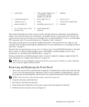
... the controller on page 115. The hard drives connect to access the internal system components. The left and ...RAID controller daughter card (optional) 4 cooling fan modules (4) 5 power supply bays (2) 6 left end of the bezel away from the system to two 3.5-inch or four 2.5-inch SAS/SATA hard drives. Removing and Replacing the Front Bezel 1 The system... more information, see "Installing a Hot-Plug Hard Drive" on page 61. Several hardware options, such as the power supplies and the hard drives. For more information, see "Installing the Optical Drive Tray" on the system board....
... the controller on page 115. The hard drives connect to access the internal system components. The left and ...RAID controller daughter card (optional) 4 cooling fan modules (4) 5 power supply bays (2) 6 left end of the bezel away from the system to two 3.5-inch or four 2.5-inch SAS/SATA hard drives. Removing and Replacing the Front Bezel 1 The system... more information, see "Installing a Hot-Plug Hard Drive" on page 61. Several hardware options, such as the power supplies and the hard drives. For more information, see "Installing the Optical Drive Tray" on the system board....
Hardware Owner's Manual (PDF)
Page 155
..., 100 battery raid, 60 bezel removing, 45-46 replacing, 46 blank hard drive, 75 power supply, 56 BMC, 41 boot device configuring, 63 boot drive configuring, 63 C CD drive... cover, 47 configuring boot drive, 63 memory, 64 connecting external devices, 15 connectors expansion-card riser board, 122 SAS backplane board, 120 SATA backplane board, 120 system board, 118 control panel assembly...closing, 47 opening, 46 removing, 46 D damaged systems troubleshooting, 99 daughter card SAS, 56 Dell contacting, 129-130 diagnostic messages, 30 diagnostics advanced testing options, 112 testing options, 112 when...
..., 100 battery raid, 60 bezel removing, 45-46 replacing, 46 blank hard drive, 75 power supply, 56 BMC, 41 boot device configuring, 63 boot drive configuring, 63 C CD drive... cover, 47 configuring boot drive, 63 memory, 64 connecting external devices, 15 connectors expansion-card riser board, 122 SAS backplane board, 120 SATA backplane board, 120 system board, 118 control panel assembly...closing, 47 opening, 46 removing, 46 D damaged systems troubleshooting, 99 daughter card SAS, 56 Dell contacting, 129-130 diagnostic messages, 30 diagnostics advanced testing options, 112 testing options, 112 when...
Hardware Owner's Manual (PDF)
Page 156
...61 installing, 61 PCIe, 61 PCI-X, 61 removing, 62 expansion slots PCI buses, 122 expansion-card riser board connectors, 122 PCI buses, 122 external devices connecting, 15 F fan modules cooling, 48 features back-panel, 14 front-panel, 11 front panel features, 11 fully buffered DIMMs memory modules, 63 G guidelines...a drive carrier, 78 hard drives boot device, 63 indicator codes, 12 SAS hard drives, 75 SATA hard drives, 75 heat sink, 68 I indicators back-panel, 14 front-panel, 11 hard-drive, 12 NIC, 16 power, 15 information you may need, 9 inside the system, 44 installing, 68 closing the cover, 47...
...61 installing, 61 PCIe, 61 PCI-X, 61 removing, 62 expansion slots PCI buses, 122 expansion-card riser board connectors, 122 PCI buses, 122 external devices connecting, 15 F fan modules cooling, 48 features back-panel, 14 front-panel, 11 front panel features, 11 fully buffered DIMMs memory modules, 63 G guidelines...a drive carrier, 78 hard drives boot device, 63 indicator codes, 12 SAS hard drives, 75 SATA hard drives, 75 heat sink, 68 I indicators back-panel, 14 front-panel, 11 hard-drive, 12 NIC, 16 power, 15 information you may need, 9 inside the system, 44 installing, 68 closing the cover, 47...


