
Information Update
Page 12
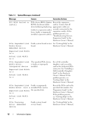
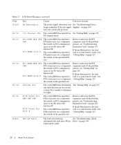
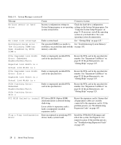
... device BIOS (Option Reseat the expansion ROM) checksum failure card(s). System Messages (continued) Message Causes Corrective Actions PCI BIOS failed to the loose; PCIe Degraded Link Faulty system board or riser See "Getting Help" in Expected Link Width the specified slot...the Hardware Owner's Manual. If the problem persists, see "Troubleshooting System Expansion Cards" in the Hardware Owner's Manual. PCIe Training Error: Embedded device Faulty system board or riser board. faulty or improperly expansion card(s). If the problem persists, see "Getting Help" in the Hardware Owner's...
... device BIOS (Option Reseat the expansion ROM) checksum failure card(s). System Messages (continued) Message Causes Corrective Actions PCI BIOS failed to the loose; PCIe Degraded Link Faulty system board or riser See "Getting Help" in Expected Link Width the specified slot...the Hardware Owner's Manual. If the problem persists, see "Troubleshooting System Expansion Cards" in the Hardware Owner's Manual. PCIe Training Error: Embedded device Faulty system board or riser board. faulty or improperly expansion card(s). If the problem persists, see "Getting Help" in the Hardware Owner's...
Information Update
Page 17
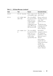
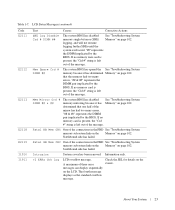
... the Hardware Owner's Manual. If the problem persists, the riser card or system board is out Check the AC of acceptable range. Information Update 17 in the Hardware Owner's Manual. PCI PERR B## D## F## The system BIOS Remove ...and reseat has reported a PCI the PCIe expansion parity error on a component that problem persists, resides in the Hardware Owner's Manual. Reinstall the expansion-card riser. If the component that resides in the specified PCIe slot. PCI PERR Slot # The system BIOS has reported a PCI parity error on...
... the Hardware Owner's Manual. If the problem persists, the riser card or system board is out Check the AC of acceptable range. Information Update 17 in the Hardware Owner's Manual. PCI PERR B## D## F## The system BIOS Remove ...and reseat has reported a PCI the PCIe expansion parity error on a component that problem persists, resides in the Hardware Owner's Manual. Reinstall the expansion-card riser. If the component that resides in the specified PCIe slot. PCI PERR Slot # The system BIOS has reported a PCI parity error on...
Information Update
Page 18
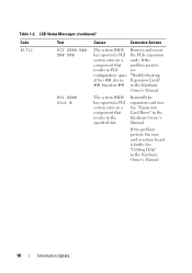
..., resides in the Hardware Owner's Manual. Reinstall the expansion-card riser. in PCI see configuration space "Troubleshooting at bus ##, device Expansion Cards" ##, function ##. If the problem persists, the riser card or system board is faulty. The system BIOS has reported a PCI system error on a cards. See "Expansion Card Risers" in the Hardware Owner's Manual. 18 Information Update See...
..., resides in the Hardware Owner's Manual. Reinstall the expansion-card riser. in PCI see configuration space "Troubleshooting at bus ##, device Expansion Cards" ##, function ##. If the problem persists, the riser card or system board is faulty. The system BIOS has reported a PCI system error on a cards. See "Expansion Card Risers" in the Hardware Owner's Manual. 18 Information Update See...
Information Update
Page 19
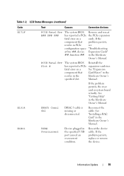
If the problem persists, see "Troubleshooting Expansion Cards" in the Hardware Owner's Manual. Reconnect the cable. If the problem persists, the riser card or system board is missing or disconnected. See "Getting Help" in the Hardware Owner's Manual. USB# Overcurrent Device... plugged in the Hardware Owner's Manual. If the problem persists, replace or remove the device. Reinstall the expansion-card riser. Reseat the device cable. Information Update 19 PCIE Fatal Err Slot # The system BIOS has reported a PCIe fatal error on a component...
If the problem persists, see "Troubleshooting Expansion Cards" in the Hardware Owner's Manual. Reconnect the cable. If the problem persists, the riser card or system board is missing or disconnected. See "Getting Help" in the Hardware Owner's Manual. USB# Overcurrent Device... plugged in the Hardware Owner's Manual. If the problem persists, replace or remove the device. Reinstall the expansion-card riser. Reseat the device cable. Information Update 19 PCIE Fatal Err Slot # The system BIOS has reported a PCIe fatal error on a component...
Hardware Owner's Manual (PDF)
Page 6
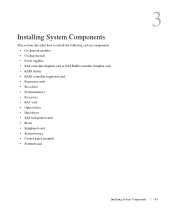
Expansion-Card Riser 82 Removing an Expansion-Card Riser 82 Installing an Expansion-Card Riser 83 Backplane Board 83 Removing the Backplane Board 83 Installing the Backplane Board 85 Sideplane Board 85 Removing the Sideplane Board 85 Installing the Sideplane ...
Expansion-Card Riser 82 Removing an Expansion-Card Riser 82 Installing an Expansion-Card Riser 83 Backplane Board 83 Removing the Backplane Board 83 Installing the Backplane Board 85 Sideplane Board 85 Removing the Sideplane Board 85 Installing the Sideplane ...
Hardware Owner's Manual (PDF)
Page 7
...Troubleshooting System Memory 102 Troubleshooting an Optical Drive 103 Troubleshooting a Hard Drive 104 Troubleshooting a SAS or SAS RAID Controller Daughter Card 105 Troubleshooting Expansion Cards 107 Troubleshooting the Microprocessors 108 5 Running the System Diagnostics Using Server Administrator Diagnostics 111 System Diagnostics Features 111 When to ... Board Jumpers 115 Disabling a Forgotten Password 117 System Board Connectors 118 SAS/SATA Backplane Board Connectors 120 Expansion-Card Riser-Board Components and PCI Buses 122 SAS Sideplane Board Connectors 123 Contents 7
...Troubleshooting System Memory 102 Troubleshooting an Optical Drive 103 Troubleshooting a Hard Drive 104 Troubleshooting a SAS or SAS RAID Controller Daughter Card 105 Troubleshooting Expansion Cards 107 Troubleshooting the Microprocessors 108 5 Running the System Diagnostics Using Server Administrator Diagnostics 111 System Diagnostics Features 111 When to ... Board Jumpers 115 Disabling a Forgotten Password 117 System Board Connectors 118 SAS/SATA Backplane Board Connectors 120 Expansion-Card Riser-Board Components and PCI Buses 122 SAS Sideplane Board Connectors 123 Contents 7
Hardware Owner's Manual (PDF)
Page 20
...BIOS has reported a PCI parity error on a component that resides in PCI configuration space at bus ##, device ##, function ##. If the problem persists, the riser card or system board is faulty. PCI SERR B## D## F## PCI SERR Slot # The system BIOS has reported a PCI system error on a component that ... system error on page 125. experienced a fault. 20 About Your System fails, the system will go down. If the problem persists, the riser card or system board is faulty. See "Getting Help" on a component that resides in the specified slot. See "Getting Help" on page 107...
...BIOS has reported a PCI parity error on a component that resides in PCI configuration space at bus ##, device ##, function ##. If the problem persists, the riser card or system board is faulty. PCI SERR B## D## F## PCI SERR Slot # The system BIOS has reported a PCI system error on a component that ... system error on page 125. experienced a fault. 20 About Your System fails, the system will go down. If the problem persists, the riser card or system board is faulty. See "Getting Help" on a component that resides in the specified slot. See "Getting Help" on page 107...
Hardware Owner's Manual (PDF)
Page 23
"## & ##" represents the DIMM pair implicated by the BIOS. determined that the memory had too many errors. Table 1-7. If no memory card is present, the "Crd #" string is left out of the message. Information only. >3 ERRs Chk Log LCD overflow message. messages can ...been removed. that one half of the message. Northbound side has failed. About Your System 23 If no memory card is present, the "Crd #" string is rebooted. If no memory riser card is present, the "Crd #" string is left out of the message. The fourth message displays as the standard...
"## & ##" represents the DIMM pair implicated by the BIOS. determined that the memory had too many errors. Table 1-7. If no memory card is present, the "Crd #" string is left out of the message. Information only. >3 ERRs Chk Log LCD overflow message. messages can ...been removed. that one half of the message. Northbound side has failed. About Your System 23 If no memory card is present, the "Crd #" string is rebooted. If no memory riser card is present, the "Crd #" string is left out of the message. The fourth message displays as the standard...
Hardware Owner's Manual (PDF)
Page 28
...the specified slot number. Plug & Play Configuration Error encountered in the System Setup program. See "Expansion-Card Riser" on page 102. Reseat the expansion card(s). If the problem persists, see "Getting Help" on hard drive No timer tick interrupt Northbound merge ...memory controller. See system on page 125." Loose cables to the expansion card(s). See "Expansion-Card Riser" on page 31. Reseat the PCIe card in the specified slot. If the problem persists, see "Troubleshooting Expansion Cards" on page 125. Faulty system board. PCIe Degraded Link Width Error...
...the specified slot number. Plug & Play Configuration Error encountered in the System Setup program. See "Expansion-Card Riser" on page 102. Reseat the expansion card(s). If the problem persists, see "Getting Help" on hard drive No timer tick interrupt Northbound merge ...memory controller. See system on page 125." Loose cables to the expansion card(s). See "Expansion-Card Riser" on page 31. Reseat the PCIe card in the specified slot. If the problem persists, see "Troubleshooting Expansion Cards" on page 125. Faulty system board. PCIe Degraded Link Width Error...
Hardware Owner's Manual (PDF)
Page 43
... shrouds • Power supplies • SAS controller daughter card or SAS RAID controller daughter card • RAID battery • RAID controller expansion card • Expansion cards • Boot drive • System memory • Processors • RAC card • Optical drive • Hard drives • SAS backplane boards • Risers • Sideplane board • System battery •...
... shrouds • Power supplies • SAS controller daughter card or SAS RAID controller daughter card • RAID battery • RAID controller expansion card • Expansion cards • Boot drive • System memory • Processors • RAC card • Optical drive • Hard drives • SAS backplane boards • Risers • Sideplane board • System battery •...
Hardware Owner's Manual (PDF)
Page 45
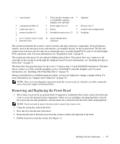
...RAID controller daughter card (optional) 4 cooling fan modules (4) 5 power supply bays (2) 6 left end of the bezel away from the system to release the right end of the bezel. 5 Pull the bezel away from the electrical outlet and peripherals. The left and center risers each have one... the system cover. 2 Using the system key, unlock the bezel. 3 Press the tab at the left end of the bezel. 4 Rotate the left riser (slot 2) 7 center riser (slot 1) 8 battery 9 system board cooling shroud 1 memory modules (8) 0 11 heatsink/microprocessor (2) 12 backplane 1 two 3.5-inch or four 2.5-inch 14...
...RAID controller daughter card (optional) 4 cooling fan modules (4) 5 power supply bays (2) 6 left end of the bezel away from the system to release the right end of the bezel. 5 Pull the bezel away from the electrical outlet and peripherals. The left and center risers each have one... the system cover. 2 Using the system key, unlock the bezel. 3 Press the tab at the left end of the bezel. 4 Rotate the left riser (slot 2) 7 center riser (slot 1) 8 battery 9 system board cooling shroud 1 memory modules (8) 0 11 heatsink/microprocessor (2) 12 backplane 1 two 3.5-inch or four 2.5-inch 14...

Hardware Owner's Manual (PDF)
Page 51
... Board Cooling Shroud 1 1 system board cooling shroud Removing the System Board Cooling Shroud 1 If applicable, remove the bezel. See "Installing an Expansion-Card Riser" on page 46. 4 Remove the memory cooling shroud. See "Closing the System" on page 53. 5 Close the system. See "Removing the Memory Cooling... See "Removing and Replacing the Front Bezel" on the front of the shroud (nearest to the front of the posts of the center and rear card risers on the motherboard. 2 Press down gently on page 45. 2 Turn off the system and attached peripherals, and then disconnect the system from the...
... Board Cooling Shroud 1 1 system board cooling shroud Removing the System Board Cooling Shroud 1 If applicable, remove the bezel. See "Installing an Expansion-Card Riser" on page 46. 4 Remove the memory cooling shroud. See "Closing the System" on page 53. 5 Close the system. See "Removing the Memory Cooling... See "Removing and Replacing the Front Bezel" on the front of the shroud (nearest to the front of the posts of the center and rear card risers on the motherboard. 2 Press down gently on page 45. 2 Turn off the system and attached peripherals, and then disconnect the system from the...

Hardware Owner's Manual (PDF)
Page 61
... 3-12. 5 Install the expansion card: a Position the expansion card so that came with the product. 1 Unpack the expansion card and prepare it for installation. PCI-X Riser Board Expansion Slots The PCI-X riser configuration provides two PCI-X slots with the expansion-card connector on separate buses). •... authorized by Dell is available with the following features: • Two PCI-X risers, installed in the left and center riser connectors. • Two x8-lane PCIe expansion slots. • Support for full height/half-length PCI cards in both slots. Expansion Cards The system...
... 3-12. 5 Install the expansion card: a Position the expansion card so that came with the product. 1 Unpack the expansion card and prepare it for installation. PCI-X Riser Board Expansion Slots The PCI-X riser configuration provides two PCI-X slots with the expansion-card connector on separate buses). •... authorized by Dell is available with the following features: • Two PCI-X risers, installed in the left and center riser connectors. • Two x8-lane PCIe expansion slots. • Support for full height/half-length PCI cards in both slots. Expansion Cards The system...

Hardware Owner's Manual (PDF)
Page 62
... is not authorized by Dell is fully seated. Damage due to the expansion card. b Insert the card-edge connector firmly into the expansion-card connector until the card is not covered by your product documentation, or as directed by a certified service technician. Installing an Expansion Card 3 2 1 5 4 1 PCI riser 4 expansion card 2 expansion-card connector 5 card-edge connector 3 expansion-card latch 6 Connect any...
... is not authorized by Dell is fully seated. Damage due to the expansion card. b Insert the card-edge connector firmly into the expansion-card connector until the card is not covered by your product documentation, or as directed by a certified service technician. Installing an Expansion Card 3 2 1 5 4 1 PCI riser 4 expansion card 2 expansion-card connector 5 card-edge connector 3 expansion-card latch 6 Connect any...

Hardware Owner's Manual (PDF)
Page 71
...and follow the safety instructions that is not authorized by Dell is not covered by the online or telephone service and support team. Figure 3-16. See "Removing an Expansion Card" on page 62. 5 Remove the center riser card from the electrical outlet. 2 Open the system. Damage ...due to the center riser. RAC Card CAUTION: Many repairs may only be done by a certified service technician. ...
...and follow the safety instructions that is not authorized by Dell is not covered by the online or telephone service and support team. Figure 3-16. See "Removing an Expansion Card" on page 62. 5 Remove the center riser card from the electrical outlet. 2 Open the system. Damage ...due to the center riser. RAC Card CAUTION: Many repairs may only be done by a certified service technician. ...

Hardware Owner's Manual (PDF)
Page 72
...over the front edge of the card until it is attached to the appropriate RAC card connector. 9 Replace the center riser card. See "Removing an Expansion Card" on page 61. 10 Close the system. See "Installing an Expansion Card" on page 62. 4 Remove the center riser card from the system board. See ...up . 6 Remove the RAC card cables from the center riser. See "Opening the System" on the front standoffs, and then lifting the RAC card up and out of the system. 8 Replace the center riser card. See "Expansion-Card Riser" on page 82. 5 Remove the RAC card cables from the system board ...
...over the front edge of the card until it is attached to the appropriate RAC card connector. 9 Replace the center riser card. See "Removing an Expansion Card" on page 61. 10 Close the system. See "Installing an Expansion Card" on page 62. 4 Remove the center riser card from the system board. See ...up . 6 Remove the RAC card cables from the center riser. See "Opening the System" on the front standoffs, and then lifting the RAC card up and out of the system. 8 Replace the center riser card. See "Expansion-Card Riser" on page 82. 5 Remove the RAC card cables from the system board ...

Hardware Owner's Manual (PDF)
Page 82
Read and follow the safety instructions that is not authorized by Dell is not covered by your product documentation, or as directed by a certified service technician. See "Removing and ...the online or telephone service and support team. Expansion-Card Riser Removal 2 3 1 4 8 7 6 5 1 left riser board 2 4 left riser board connectors (2) 5 7 center riser board 8 left riser board release 3 latches (2) center riser board connector 6 center riser board release latch left riser board alignment pins (2) center riser board alignment pins (2) 82 Installing System Components You...
Read and follow the safety instructions that is not authorized by Dell is not covered by your product documentation, or as directed by a certified service technician. See "Removing and ...the online or telephone service and support team. Expansion-Card Riser Removal 2 3 1 4 8 7 6 5 1 left riser board 2 4 left riser board connectors (2) 5 7 center riser board 8 left riser board release 3 latches (2) center riser board connector 6 center riser board release latch left riser board alignment pins (2) center riser board alignment pins (2) 82 Installing System Components You...
Hardware Owner's Manual (PDF)
Page 83
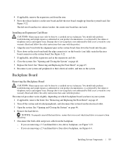
...backplane, see Figure 6-4. NOTICE: To properly reinstall the hard drives, ensure that is not authorized by Dell is not covered by your product documentation, or as authorized in the expansion-card slot. 4 Close the system. Damage due to their electrical outlets, and turn on which backplane .... 5 Disconnect the SAS cable and power cable from the electrical outlet. 3 Open the system. If you are ) fully seated in the riser board connector on the system board. See "Removing and Replacing the Front Bezel" on page 45. 6 Reconnect your warranty. Backplane Board Removing...
...backplane, see Figure 6-4. NOTICE: To properly reinstall the hard drives, ensure that is not authorized by Dell is not covered by your product documentation, or as authorized in the expansion-card slot. 4 Close the system. Damage due to their electrical outlets, and turn on which backplane .... 5 Disconnect the SAS cable and power cable from the electrical outlet. 3 Open the system. If you are ) fully seated in the riser board connector on the system board. See "Removing and Replacing the Front Bezel" on page 45. 6 Reconnect your warranty. Backplane Board Removing...
Getting Started Guide
Page 5
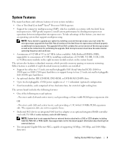
...8226; Dedicated PCI slot for an integrated SAS host bus adapter or an optional integrated RAID controller card with two Intel Xeon microprocessors. Two riser cards (left and center risers), each providing a x8 lane width PCI-Express expansion slot. NOTE: System boot is available if.... OR - Both microprocessors must use an operating system that supports multiprocessing. See support.dell.com for performing the upgrade. Either feature is not supported from Dell. To take advantage of the Intel Xeon microprocessor will work properly as the instructions for...
...8226; Dedicated PCI slot for an integrated SAS host bus adapter or an optional integrated RAID controller card with two Intel Xeon microprocessors. Two riser cards (left and center risers), each providing a x8 lane width PCI-Express expansion slot. NOTE: System boot is available if.... OR - Both microprocessors must use an operating system that supports multiprocessing. See support.dell.com for performing the upgrade. Either feature is not supported from Dell. To take advantage of the Intel Xeon microprocessor will work properly as the instructions for...
Getting Started Guide
Page 11
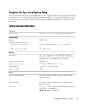
... operating system documentation that ships with your system. Technical Specifications Processor Processor type Expansion Bus Bus type Expansion slots via riser card: PCI-X Center and Left Risers or PCIe Center and Left Risers Memory Architecture Memory module sockets Memory module capacities Minimum RAM Maximum RAM Drives SAS or SATA hard drives or SAS hard...
... operating system documentation that ships with your system. Technical Specifications Processor Processor type Expansion Bus Bus type Expansion slots via riser card: PCI-X Center and Left Risers or PCIe Center and Left Risers Memory Architecture Memory module sockets Memory module capacities Minimum RAM Maximum RAM Drives SAS or SATA hard drives or SAS hard...


