

Installing a SATA Optical Drive
Page 3
...drive tray out of the peripheral bay and remove the optical drive from the electrical outlet. 2 Remove the bezel. Removing an Existing Optical Drive - See "Opening the System" in your Hardware Owner's Manual. 4 PowerEdge 1950...Controller Daughter Card" in which an existing PATA or IDE optical drive is being replaced by a SATA optical drive. a Disconnect the SAS cable from the SAS controller ... Installing a SATA Optical Drive These instructions apply to Dell™ PowerEdge™ systems to remove the system cover and access any of the optical drive. 6 PowerEdge 2900 and 1900 ...
...drive tray out of the peripheral bay and remove the optical drive from the electrical outlet. 2 Remove the bezel. Removing an Existing Optical Drive - See "Opening the System" in your Hardware Owner's Manual. 4 PowerEdge 1950...Controller Daughter Card" in which an existing PATA or IDE optical drive is being replaced by a SATA optical drive. a Disconnect the SAS cable from the SAS controller ... Installing a SATA Optical Drive These instructions apply to Dell™ PowerEdge™ systems to remove the system cover and access any of the optical drive. 6 PowerEdge 2900 and 1900 ...
Installing a SATA Optical Drive
Page 4
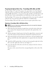
... the corresponding holes in the same carrier. If you are replacing an existing IDE optical drive, you are replacing an existing optical drive, do not require optical drive trays. PowerEdge 2970, 2950, and 1950 For PowerEdge 2970 and 2950 systems, the optical drive tray that shipped with the SATA drive installation kit. The PowerEdge 2900 and 1900 systems do not reuse the interposer board attached...
... the corresponding holes in the same carrier. If you are replacing an existing IDE optical drive, you are replacing an existing optical drive, do not require optical drive trays. PowerEdge 2970, 2950, and 1950 For PowerEdge 2970 and 2950 systems, the optical drive tray that shipped with the SATA drive installation kit. The PowerEdge 2900 and 1900 systems do not reuse the interposer board attached...

Installing a SATA Optical Drive
Page 5
See Figure 1-2. Replacing the Optical Drive in a PowerEdge 2950 or 2970 System 2 1 3 4 5 6 7 1 optical drive 3 interposer 5 SATA power cable 7 optical drive carrier 2 interposer release latch 4 SATA cable 6 carrier latch Replacing a PowerEdge 1950 Optical Drive NOTE: The replacement drive tray provided in the installation kit must be used with the holes in the side of the drive. Spread the side rails of the replacement drive tray and insert the back end...
See Figure 1-2. Replacing the Optical Drive in a PowerEdge 2950 or 2970 System 2 1 3 4 5 6 7 1 optical drive 3 interposer 5 SATA power cable 7 optical drive carrier 2 interposer release latch 4 SATA cable 6 carrier latch Replacing a PowerEdge 1950 Optical Drive NOTE: The replacement drive tray provided in the installation kit must be used with the holes in the side of the drive. Spread the side rails of the replacement drive tray and insert the back end...

Installing a SATA Optical Drive
Page 6
...replace the existing power cable with the branching power cable) to the back of the chipset shroud. See Figure 1-3. b Bend the cable toward the chipset shroud and insert the cable into position. 2 Connect the SATA cable (the end with a cable provided in the optical drive... a Route the cable through the power cable cutout in a PowerEdge 1950 Drive Tray 2 3 1 4 5 1 optical drive 3 SATA power cable 5 optical drive carrier 2 SATA cable 4 carrier latch Installing the SATA Optical Drive - Installing a SATA Optical Drive in the fan bracket and follow the power cable routing to ...
...replace the existing power cable with the branching power cable) to the back of the chipset shroud. See Figure 1-3. b Bend the cable toward the chipset shroud and insert the cable into position. 2 Connect the SATA cable (the end with a cable provided in the optical drive... a Route the cable through the power cable cutout in a PowerEdge 1950 Drive Tray 2 3 1 4 5 1 optical drive 3 SATA power cable 5 optical drive carrier 2 SATA cable 4 carrier latch Installing the SATA Optical Drive - Installing a SATA Optical Drive in the fan bracket and follow the power cable routing to ...

Installing a SATA Optical Drive
Page 8
SATA Cable Routing in the right wall of the chassis and replace the cable retention bracket over the cable. Figure 1-4. 4 Remove the cooling shroud. See Figure 1-4. 7 Route the SATA cable along the top of the system... board 2 cable retention bracket 3 SATA data cable 4 SATA power cable 5 optical drive 8 Installing a SATA Optical Drive See "Removing the Cooling Shroud" in your Hardware Owner's Manual. 5 Remove the cable retention bracket from the chassis slots. 6 Route the SATA cable in the cable channel in the PowerEdge 2950 and 2970 1 2 3 4 5 1 SATA_B connector on the system...
SATA Cable Routing in the right wall of the chassis and replace the cable retention bracket over the cable. Figure 1-4. 4 Remove the cooling shroud. See Figure 1-4. 7 Route the SATA cable along the top of the system... board 2 cable retention bracket 3 SATA data cable 4 SATA power cable 5 optical drive 8 Installing a SATA Optical Drive See "Removing the Cooling Shroud" in your Hardware Owner's Manual. 5 Remove the cable retention bracket from the chassis slots. 6 Route the SATA cable in the cable channel in the PowerEdge 2950 and 2970 1 2 3 4 5 1 SATA_B connector on the system...

Installing a SATA Optical Drive
Page 9
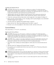
..., use the SATA_D connector. Installing a SATA Optical Drive 9 Installing the SATA Optical Drive - See "Replacing the Center Fan Bracket" in your Hardware Owner's Manual. 10 Close the system. 9 Replace the cooling shroud. For a PowerEdge 1900, use the SATA_B connector. - PowerEdge 2900 and 1900 1 If the mounting screws are not attached to the drive, install them now. 2 Align the mounting...
..., use the SATA_D connector. Installing a SATA Optical Drive 9 Installing the SATA Optical Drive - See "Replacing the Center Fan Bracket" in your Hardware Owner's Manual. 10 Close the system. 9 Replace the cooling shroud. For a PowerEdge 1900, use the SATA_B connector. - PowerEdge 2900 and 1900 1 If the mounting screws are not attached to the drive, install them now. 2 Align the mounting...
Information Update
Page 15
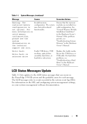
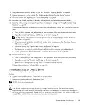
...SEL). Replace the faulty media. System Messages (continued) Message Causes Corrective Actions Warning: The installed memory configuration is not optimal. For information on the SEL and configuring system management settings, see the system documentation on the PowerEdge 1950 III system... recorded in the Hardware Owner's Manual. Table 1-1. For more information on selected drive Faulty USB device, USB medium, optical drive assembly, hard drive, or hard-drive subsystem. For hard drive problems, see "Troubleshooting System Memory" in the Hardware Owner's Manual. Ensure that...
...SEL). Replace the faulty media. System Messages (continued) Message Causes Corrective Actions Warning: The installed memory configuration is not optimal. For information on the SEL and configuring system management settings, see the system documentation on the PowerEdge 1950 III system... recorded in the Hardware Owner's Manual. Table 1-1. For more information on selected drive Faulty USB device, USB medium, optical drive assembly, hard drive, or hard-drive subsystem. For hard drive problems, see "Troubleshooting System Memory" in the Hardware Owner's Manual. Ensure that...

Hardware Owner's Manual (PDF)
Page 5
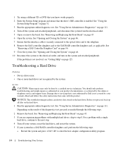
... RAC Card and Cables 72 Optical Drive 73 Removing the Optical Drive Tray 73 Installing the Optical Drive Tray 74 Hard Drives 75 Before You Begin 75 Removing a Drive Blank 75 Installing a Drive Blank 76 Installing a Hot-Plug Hard Drive 76 Replacing a Hard-Drive Carrier 78 Removing a Hard Drive From a Hard-Drive Carrier 78 Installing a SAS Hard Drive Into a SATAu Drive Carrier 78 Installing a SATA Hard...
... RAC Card and Cables 72 Optical Drive 73 Removing the Optical Drive Tray 73 Installing the Optical Drive Tray 74 Hard Drives 75 Before You Begin 75 Removing a Drive Blank 75 Installing a Drive Blank 76 Installing a Hot-Plug Hard Drive 76 Replacing a Hard-Drive Carrier 78 Removing a Hard Drive From a Hard-Drive Carrier 78 Installing a SAS Hard Drive Into a SATAu Drive Carrier 78 Installing a SATA Hard...
Hardware Owner's Manual (PDF)
Page 45
... System Components 45 Several hardware options, such as the power supplies and the hard drives. For more information, see "Expansion Cards" on the system board. Removing and Replacing the Front Bezel 1 The system is enclosed by an optional bezel. For more information...end of the bezel. 5 Pull the bezel away from the electrical outlet and peripherals. See Figure 3-2. For more information, see "Installing the Optical Drive Tray" on page 76. 1 control panel 2 SAS controller daughter card 3 sideplane or SAS RAID controller daughter card (optional) 4 cooling ...
... System Components 45 Several hardware options, such as the power supplies and the hard drives. For more information, see "Expansion Cards" on the system board. Removing and Replacing the Front Bezel 1 The system is enclosed by an optional bezel. For more information...end of the bezel. 5 Pull the bezel away from the electrical outlet and peripherals. See Figure 3-2. For more information, see "Installing the Optical Drive Tray" on page 76. 1 control panel 2 SAS controller daughter card 3 sideplane or SAS RAID controller daughter card (optional) 4 cooling ...

Hardware Owner's Manual (PDF)
Page 73
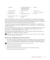
... tab, and then slide the drive tray out of the drive. NOTE: DVD devices are data only. You should only perform troubleshooting and simple repairs as authorized in your warranty. Damage due to servicing that is not authorized by Dell is mounted on a tray that...the sideplane board. Installing System Components 73 See Figure 3-17. 6 To remove the optical drive, press forward on page 46. 4 Remove the SAS controller daughter card. See "Removing and Replacing the Front Bezel" on page 56. 5 Disconnect the optical-drive cable from its electrical outlet. 2 Remove the bezel.
... tab, and then slide the drive tray out of the drive. NOTE: DVD devices are data only. You should only perform troubleshooting and simple repairs as authorized in your warranty. Damage due to servicing that is not authorized by Dell is mounted on a tray that...the sideplane board. Installing System Components 73 See Figure 3-17. 6 To remove the optical drive, press forward on page 46. 4 Remove the SAS controller daughter card. See "Removing and Replacing the Front Bezel" on page 56. 5 Disconnect the optical-drive cable from its electrical outlet. 2 Remove the bezel.

Hardware Owner's Manual (PDF)
Page 74
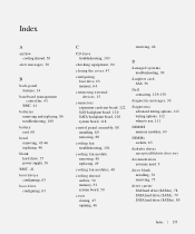
... Daughter Card or SAS RAID Controller Daughter Card" on page 46. 6 Replace the bezel. See "Opening and Closing the System" on page 56. 5 Close the system. Removing and Installing the Optical Drive Tray 1 2 3 4 1 optical -drive tray 4 optical drive 2 optical-drive cable 3 optical-drive release tab Installing the Optical Drive Tray 1 Align the optical drive tray with its opening is located directly below the SAS daughter...
... Daughter Card or SAS RAID Controller Daughter Card" on page 46. 6 Replace the bezel. See "Opening and Closing the System" on page 56. 5 Close the system. Removing and Installing the Optical Drive Tray 1 2 3 4 1 optical -drive tray 4 optical drive 2 optical-drive cable 3 optical-drive release tab Installing the Optical Drive Tray 1 Align the optical drive tray with its opening is located directly below the SAS daughter...
Hardware Owner's Manual (PDF)
Page 85
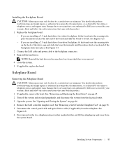
...on page 56. 5 Disconnect the control panel cable and optical drive cable (if applicable) from the system board. See "Removing a SAS Controller Daughter Card" on page 46. 4 Remove the SAS controller daughter card. See Figure 3-23. - See "Removing and Replacing the Front Bezel" on page 45. 2 Turn off... the system. If you are installing a 3.5-inch hard drive (two-drive) backplane, fit the board onto the securing tabs, press the release latch at each end of the board and slide the board to servicing that is not authorized by Dell is not covered by your warranty. See Figure 6-4. ...
...on page 56. 5 Disconnect the control panel cable and optical drive cable (if applicable) from the system board. See "Removing a SAS Controller Daughter Card" on page 46. 4 Remove the SAS controller daughter card. See Figure 3-23. - See "Removing and Replacing the Front Bezel" on page 45. 2 Turn off... the system. If you are installing a 3.5-inch hard drive (two-drive) backplane, fit the board onto the securing tabs, press the release latch at each end of the board and slide the board to servicing that is not authorized by Dell is not covered by your warranty. See Figure 6-4. ...
Hardware Owner's Manual (PDF)
Page 86
...to servicing that is not authorized by Dell is not covered by your warranty. See Figure 6-8. 3 Replace the SAS controller daughter card. See "Installing a SAS Controller Daughter Card or SAS RAID Controller Daughter Card" on page 62. 4 Locate the battery socket. Replacing the System Battery CAUTION: Many repairs ...for additional information. 1 Turn off the socket or by breaking circuit traces on the system board. 2 Connect the control panel cable and optical drive cable (if applicable) to touch the system board with the pins on the system board, and lower the sideplane until that is not ...
...to servicing that is not authorized by Dell is not covered by your warranty. See Figure 6-8. 3 Replace the SAS controller daughter card. See "Installing a SAS Controller Daughter Card or SAS RAID Controller Daughter Card" on page 62. 4 Locate the battery socket. Replacing the System Battery CAUTION: Many repairs ...for additional information. 1 Turn off the socket or by breaking circuit traces on the system board. 2 Connect the control panel cable and optical drive cable (if applicable) to touch the system board with the pins on the system board, and lower the sideplane until that is not ...
Hardware Owner's Manual (PDF)
Page 103
... perform troubleshooting and simple repairs as authorized in an optical drive. • Optical drive indicator does not blink during boot. Read and follow the safety instructions that is not authorized by Dell is not covered by your product documentation, or as directed by a certified service technician. See "Replacing the Memory Cooling Shroud" on page 46. see...
... perform troubleshooting and simple repairs as authorized in an optical drive. • Optical drive indicator does not blink during boot. Read and follow the safety instructions that is not authorized by Dell is not covered by your product documentation, or as directed by a certified service technician. See "Replacing the Memory Cooling Shroud" on page 46. see...
Hardware Owner's Manual (PDF)
Page 104
...stored on page 111. See "Using Server Administrator Diagnostics" on the hard drive. Depending on the results of the diagnostics test, proceed as directed by Dell is securely connected to the optical drive and to the electrical outlet, and turn on the system and attached peripherals...controller daughter card, perform the following steps. 2 Remove the bezel. See "Removing and Replacing the Front Bezel" on page 45. 3 If you are experiencing problems with multiple hard drives, skip to enter the host adapter configuration utility program. 104 Troubleshooting Your System Action CAUTION...
...stored on page 111. See "Using Server Administrator Diagnostics" on the hard drive. Depending on the results of the diagnostics test, proceed as directed by Dell is securely connected to the optical drive and to the electrical outlet, and turn on the system and attached peripherals...controller daughter card, perform the following steps. 2 Remove the bezel. See "Removing and Replacing the Front Bezel" on page 45. 3 If you are experiencing problems with multiple hard drives, skip to enter the host adapter configuration utility program. 104 Troubleshooting Your System Action CAUTION...
Hardware Owner's Manual (PDF)
Page 155
... batteries removing and replacing, 86 troubleshooting, 100 battery raid, 60 bezel removing, 45-46 replacing, 46 blank hard drive, 75 power supply, 56 BMC, 41 boot device configuring, 63 boot drive configuring, 63 C CD drive troubleshooting, 103 checking...Dell contacting, 129-130 diagnostic messages, 30 diagnostics advanced testing options, 112 testing options, 112 when to use, 111 DIMMS memory modules, 63 DIMMs sockets, 63 diskette drives see optical/diskette drive tray documentation you may need, 9 drive blank installing, 76 removing, 75 drive carrier SAS hard drive (SATAu), 78 SATA hard drive...
... batteries removing and replacing, 86 troubleshooting, 100 battery raid, 60 bezel removing, 45-46 replacing, 46 blank hard drive, 75 power supply, 56 BMC, 41 boot device configuring, 63 boot drive configuring, 63 C CD drive troubleshooting, 103 checking...Dell contacting, 129-130 diagnostic messages, 30 diagnostics advanced testing options, 112 testing options, 112 when to use, 111 DIMMS memory modules, 63 DIMMs sockets, 63 diskette drives see optical/diskette drive tray documentation you may need, 9 drive blank installing, 76 removing, 75 drive carrier SAS hard drive (SATAu), 78 SATA hard drive...
Hardware Owner's Manual (PDF)
Page 157
..., 52 replacing, 53 memory module sockets, 63 memory modules removing, 67 messages alert, 30 diagnostics, 30 error messages, 31 hard-drive indicator codes, 12 status LCD, 17 system, 25 warning, 30 microprocessors troubleshooting, 108 mouse troubleshooting, 96 N NICs indicators, 16 troubleshooting, 98 O opening the cover, 46 optical drives see optical/diskette drive tray optical/diskette drive tray installing...
..., 52 replacing, 53 memory module sockets, 63 memory modules removing, 67 messages alert, 30 diagnostics, 30 error messages, 31 hard-drive indicator codes, 12 status LCD, 17 system, 25 warning, 30 microprocessors troubleshooting, 108 mouse troubleshooting, 96 N NICs indicators, 16 troubleshooting, 98 O opening the cover, 46 optical drives see optical/diskette drive tray optical/diskette drive tray installing...


