
Information Update
Page 3
... Monitoring Features 5 New I/O and Storage Features 6 New Security Features 6 Optional Internal USB Memory Key 6 Installing the Optional Internal USB Memory Key . . 8 Support for 8-GB Memory Modules - Safeguarding Encrypted Data 10 System Message Update 10 LCD Status Messages Update 15 Contents 3 PowerEdge 1950 III Systems 9 Processor Upgrades - PowerEdge 1950 II and PowerEdge 1950 III Systems 9 System Board Replacement - Contents Non-Optimal...
... Monitoring Features 5 New I/O and Storage Features 6 New Security Features 6 Optional Internal USB Memory Key 6 Installing the Optional Internal USB Memory Key . . 8 Support for 8-GB Memory Modules - Safeguarding Encrypted Data 10 System Message Update 10 LCD Status Messages Update 15 Contents 3 PowerEdge 1950 III Systems 9 Processor Upgrades - PowerEdge 1950 II and PowerEdge 1950 III Systems 9 System Board Replacement - Contents Non-Optimal...
Information Update
Page 9
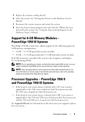
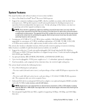
... displays 63.75 GB during POST. Information Update 9 PowerEdge 1950 III Systems PowerEdge 1950 III systems have added support for 8-GB Memory Modules - NOTE: Some operating systems cannot support more information on the latest processor upgrade options for your system. Support for the following approved...the system. For more than 4 GB of memory is fully supported. See "Closing the System" in the Hardware Owner's Manual. 5 Replace the memory cooling shroud. 6 Close the system. See support.dell.com for information on memory support requirements and restrictions, refer to power and...
... displays 63.75 GB during POST. Information Update 9 PowerEdge 1950 III Systems PowerEdge 1950 III systems have added support for 8-GB Memory Modules - NOTE: Some operating systems cannot support more information on the latest processor upgrade options for your system. Support for the following approved...the system. For more than 4 GB of memory is fully supported. See "Closing the System" in the Hardware Owner's Manual. 5 Replace the memory cooling shroud. 6 Close the system. See support.dell.com for information on memory support requirements and restrictions, refer to power and...

Hardware Owner's Manual (PDF)
Page 26
... reduced ECC protection. Dual-rank DIMM paired with each other. See "System a single-rank DIMM. Error: Incorrect memory configuration. Faulty or improperly seated memory See "Troubleshooting System Memory" module(s). memory upgrade kits directly from www.dell.com or your Dell sales agent to its location. The system has are of the same type and size and that...
... reduced ECC protection. Dual-rank DIMM paired with each other. See "System a single-rank DIMM. Error: Incorrect memory configuration. Faulty or improperly seated memory See "Troubleshooting System Memory" module(s). memory upgrade kits directly from www.dell.com or your Dell sales agent to its location. The system has are of the same type and size and that...
Hardware Owner's Manual (PDF)
Page 29
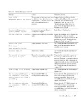
... Requested sector not found Seek error Seek operation failed Faulty diskette or hard drive. Retry Remote Configuration. If memory has not been added or removed, check the SEL to ensure compatibility. Dell recommends purchasing memory upgrade kits directly from Replace the diskette. DIMM y Ensure that faulty. Table 1-8. See "Troubleshooting disk, or the requested sector...
... Requested sector not found Seek error Seek operation failed Faulty diskette or hard drive. Retry Remote Configuration. If memory has not been added or removed, check the SEL to ensure compatibility. Dell recommends purchasing memory upgrade kits directly from Replace the diskette. DIMM y Ensure that faulty. Table 1-8. See "Troubleshooting disk, or the requested sector...

Hardware Owner's Manual (PDF)
Page 31
... configuration stored in NVRAM after you add, change, or remove hardware • Set or change information on page 25 for correcting errors. NOTE: After installing a memory upgrade, it is booting, make a note of the message and suggestions for an explanation of the message. If an error message appears while the system is...
... configuration stored in NVRAM after you add, change, or remove hardware • Set or change information on page 25 for correcting errors. NOTE: After installing a memory upgrade, it is booting, make a note of the message and suggestions for an explanation of the message. If an error message appears while the system is...
Hardware Owner's Manual (PDF)
Page 45
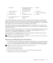
...release the right end of the bezel. 4 Rotate the left riser (slot 2) 7 center riser (slot 1) 8 battery 9 system board cooling shroud 1 memory modules (8) 0 11 heatsink/microprocessor (2) 12 backplane 1 two 3.5-inch or four 2.5-inch 14 optical slimline drive 3 hard drive bays (optional) The system...The hard drives connect to the controller on page 76. To upgrade or troubleshoot the system, remove the bezel and cover to change a jumper setting. Several hardware options, such as the microprocessors and memory, are no hot-pluggable components inside this system except for ...
...release the right end of the bezel. 4 Rotate the left riser (slot 2) 7 center riser (slot 1) 8 battery 9 system board cooling shroud 1 memory modules (8) 0 11 heatsink/microprocessor (2) 12 backplane 1 two 3.5-inch or four 2.5-inch 14 optical slimline drive 3 hard drive bays (optional) The system...The hard drives connect to the controller on page 76. To upgrade or troubleshoot the system, remove the bezel and cover to change a jumper setting. Several hardware options, such as the microprocessors and memory, are no hot-pluggable components inside this system except for ...

Hardware Owner's Manual (PDF)
Page 46
... 2 Remove the bezel. Figure 3-2. To avoid injury, do not attempt to servicing that came with the product. Opening the System To upgrade or troubleshoot the system, remove the system cover to gain access to cool before handling. See "Removing and Replacing the Front Bezel" on... steps in your warranty. Read and follow the safety instructions that is not authorized by Dell is not covered by the online or telephone service and support team. CAUTION: The memory modules can become extremely hot during normal operation. See Figure 3-3. 46 Installing System Components You...
... 2 Remove the bezel. Figure 3-2. To avoid injury, do not attempt to servicing that came with the product. Opening the System To upgrade or troubleshoot the system, remove the system cover to gain access to cool before handling. See "Removing and Replacing the Front Bezel" on... steps in your warranty. Read and follow the safety instructions that is not authorized by Dell is not covered by the online or telephone service and support team. CAUTION: The memory modules can become extremely hot during normal operation. See Figure 3-3. 46 Installing System Components You...
Hardware Owner's Manual (PDF)
Page 63
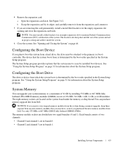
... the primary (or boot) controller. The System Setup program provides options that the system boots from Dell. See "Using the System Setup Program" on the system board under the memory cooling shroud.You can upgrade your original memory modules from a hard drive, the drive must install a filler bracket over the empty expansion slot opening...
... the primary (or boot) controller. The System Setup program provides options that the system boots from Dell. See "Using the System Setup Program" on the system board under the memory cooling shroud.You can upgrade your original memory modules from a hard drive, the drive must install a filler bracket over the empty expansion slot opening...

Hardware Owner's Manual (PDF)
Page 67
... out of the socket. Read and follow the safety instructions that came with the product. 1 Prior to upgrading your warranty. CAUTION: The memory modules are included in the processor upgrade kit: • Processor • Heat sink Removing the Processor CAUTION: Many repairs may only be done by... support.dell.com. See "Replacing the Memory Cooling Shroud" on page 46. 2 Remove the memory cooling shroud. Allow time for some time after the system has been powered down and out on the ejectors on each memory module only on the system board. Processors You can upgrade your ...
... out of the socket. Read and follow the safety instructions that came with the product. 1 Prior to upgrading your warranty. CAUTION: The memory modules are included in the processor upgrade kit: • Processor • Heat sink Removing the Processor CAUTION: Many repairs may only be done by... support.dell.com. See "Replacing the Memory Cooling Shroud" on page 46. 2 Remove the memory cooling shroud. Allow time for some time after the system has been powered down and out on the ejectors on each memory module only on the system board. Processors You can upgrade your ...
Hardware Owner's Manual (PDF)
Page 157
...system features, 10 power indicator, 15 power supplies removing, 54 replacing, 55 troubleshooting, 100 power supply blank, 56 processor installing, 69 replacing, 67 upgrades, 67 R RAC card installing, 71 RAID battery installing, 60 removing, 60 raid battery, 60 RAID controller (integrated) troubleshooting, 105 recommended tools, 44... assembly, 88 cooling fan module, 48 cover, 46 expansion card, 62 hard drive blank, 75 hard drive from a drive carrier, 78 memory, 67 optical/diskette drive tray, 73 power supply, 54 power supply blank, 56 RAID battery, 60 risers, 82 SAS controller daughter card,...
...system features, 10 power indicator, 15 power supplies removing, 54 replacing, 55 troubleshooting, 100 power supply blank, 56 processor installing, 69 replacing, 67 upgrades, 67 R RAC card installing, 71 RAID battery installing, 60 removing, 60 raid battery, 60 RAID controller (integrated) troubleshooting, 105 recommended tools, 44... assembly, 88 cooling fan module, 48 cover, 46 expansion card, 62 hard drive blank, 75 hard drive from a drive carrier, 78 memory, 67 optical/diskette drive tray, 73 power supply, 54 power supply blank, 56 RAID battery, 60 risers, 82 SAS controller daughter card,...
Hardware Owner's Manual (PDF)
Page 159
damaged system, 99 expansion card, 107 external connections, 94 keyboard, 95 memory, 102 microprocessors, 108 mouse, 96 NIC, 98 power supplies, 100 RAID controller (integrated), 105 SAS hard drive, 104 serial I/O device, 97 start-up routine, 93 system cooling, 101 USB device, 97 video, 95 wet system, 98 U upgrades processor, 67 USB device troubleshooting, 97 using system setup, 31 V video troubleshooting, 95 W warning messages, 30 wet system troubleshooting, 98 Z ZIF socket, 67 Index 159
damaged system, 99 expansion card, 107 external connections, 94 keyboard, 95 memory, 102 microprocessors, 108 mouse, 96 NIC, 98 power supplies, 100 RAID controller (integrated), 105 SAS hard drive, 104 serial I/O device, 97 start-up routine, 93 system cooling, 101 USB device, 97 video, 95 wet system, 98 U upgrades processor, 67 USB device troubleshooting, 97 using system setup, 31 V video troubleshooting, 95 W warning messages, 30 wet system troubleshooting, 98 Z ZIF socket, 67 Index 159
Getting Started Guide
Page 5
The upgrade kit from Dell contains the correct version of the microprocessor as well as additional microprocessors. The system also features redundant memory, which is available on systems with 256 MB of the Intel Xeon microprocessor will work properly as the...you must order the microprocessor upgrade kits from Dell. Two riser cards (left and center risers), each providing a 3.3V, 64-bit 133MHz PCI-X expansion slot. See support.dell.com for symmetric multiprocessing (SMP), which provides memory sparing or memory mirroring. Not all versions of cache memory and a RAID battery. ...
The upgrade kit from Dell contains the correct version of the microprocessor as well as additional microprocessors. The system also features redundant memory, which is available on systems with 256 MB of the Intel Xeon microprocessor will work properly as the...you must order the microprocessor upgrade kits from Dell. Two riser cards (left and center risers), each providing a 3.3V, 64-bit 133MHz PCI-X expansion slot. See support.dell.com for symmetric multiprocessing (SMP), which provides memory sparing or memory mirroring. Not all versions of cache memory and a RAID battery. ...


