

Getting Started Guide
Page 5
...software if the top cover is a 3.3-V, PCIe x8 lane; To take advantage of this feature, you must order the processor upgrade kits from Dell contains the correct version of the processor and heat sink. • A minimum of 512 MB of 533 or 667 MHz (when available), Fully Buffered DIMMs... (FBD), upgradable to a maximum of the Intel Xeon processor will work properly as additional processors. The system board includes the following ...
...software if the top cover is a 3.3-V, PCIe x8 lane; To take advantage of this feature, you must order the processor upgrade kits from Dell contains the correct version of the processor and heat sink. • A minimum of 512 MB of 533 or 667 MHz (when available), Fully Buffered DIMMs... (FBD), upgradable to a maximum of the Intel Xeon processor will work properly as additional processors. The system board includes the following ...
Getting Started Guide
Page 11
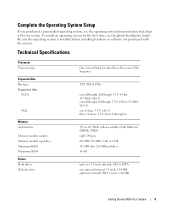
... the 0perating System Setup If you purchased a preinstalled operating system, see the Quick Installation Guide. Technical Specifications Processor Processor type Expansion Bus Bus type Expansion slots PCI-X PCIe Memory Architecture Memory module sockets Memory module capacities Minimum RAM... Maximum RAM Drives Hard drives Diskette drive One or two Dual-Core Intel Xeon Processors 5000 Sequence PCI, PCI-X, PCIe one full-height, half-length 3.3-V, 64-bit, 133-MHz (slot 1) one full-height, full-length 3.3-V,...
... the 0perating System Setup If you purchased a preinstalled operating system, see the Quick Installation Guide. Technical Specifications Processor Processor type Expansion Bus Bus type Expansion slots PCI-X PCIe Memory Architecture Memory module sockets Memory module capacities Minimum RAM... Maximum RAM Drives Hard drives Diskette drive One or two Dual-Core Intel Xeon Processors 5000 Sequence PCI, PCI-X, PCIe one full-height, half-length 3.3-V, 64-bit, 133-MHz (slot 1) one full-height, full-length 3.3-V,...

Hardware Owner's Manual (PDF)
Page 5
... Memory Mirroring Support 83 Installing Memory Modules 83 Removing Memory Modules 85 Installing a RAC Card 85 Activating the Integrated NIC TOE 87 Microprocessor 87 Replacing a Processor 88 SAS RAID Controller Daughter Card 92 Replacing the SAS RAID Controller Daughter Card Battery 92 Removing the SAS RAID Controller Daughter Card 93 Installing...
... Memory Mirroring Support 83 Installing Memory Modules 83 Removing Memory Modules 85 Installing a RAC Card 85 Activating the Integrated NIC TOE 87 Microprocessor 87 Replacing a Processor 88 SAS RAID Controller Daughter Card 92 Replacing the SAS RAID Controller Daughter Card Battery 92 Removing the SAS RAID Controller Daughter Card 93 Installing...
Hardware Owner's Manual (PDF)
Page 17
...If the problem persists, see "Getting Help" on page 131. A voltage regulator failure was detected when the processor regulator(s) was enabled See "Getting Help" on page 109. failed. Controller Daughter Card Battery" on page 92..., and "Troubleshooting System Cooling Problems" on page 131. Processor # VCORE voltage regulator has failed. See "Getting Help" on page 131. 0.9 V regulator voltage has exceeded the...'s Information Update Tech Sheet located on support.dell.com for the most current system information.
...If the problem persists, see "Getting Help" on page 131. A voltage regulator failure was detected when the processor regulator(s) was enabled See "Getting Help" on page 109. failed. Controller Daughter Card Battery" on page 92..., and "Troubleshooting System Cooling Problems" on page 131. Processor # VCORE voltage regulator has failed. See "Getting Help" on page 131. 0.9 V regulator voltage has exceeded the...'s Information Update Tech Sheet located on support.dell.com for the most current system information.
Hardware Owner's Manual (PDF)
Page 18
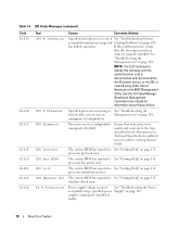
..." on page 118. If the problem persists, ensure that your system's Getting Started Guide. See the Dell OpenManage Baseboard Management Controller User's Guide for information about these utilities. Processors are properly installed. The system BIOS has reported a See "Getting Help" on page 131. The system... to the type described in the Microprocessor Technical Specifications outlined in your processors match and conform to the AC power source, or the SEL is in a configuration unsupported by Dell. Specified processor is missing or See "Troubleshooting the bad, and the system is ...
..." on page 118. If the problem persists, ensure that your system's Getting Started Guide. See the Dell OpenManage Baseboard Management Controller User's Guide for information about these utilities. Processors are properly installed. The system BIOS has reported a See "Getting Help" on page 131. The system... to the type described in the Microprocessor Technical Specifications outlined in your processors match and conform to the AC power source, or the SEL is in a configuration unsupported by Dell. Specified processor is missing or See "Troubleshooting the bad, and the system is ...
Hardware Owner's Manual (PDF)
Page 29
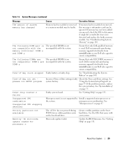
... has not been added or removed, check the SEL to ensure compatibility. See "Troubleshooting System Memory" on page 108. Ensure that only Dell-qualified memory is used . Time-of -day not set please run SETUP program Incorrect Time or Date settings; See "Troubleshooting the System ...battery. Create a utility partition on page 131. See the CDs that only ECC FBD1 memory is used . No microcode update loaded for processor n Microcode update failed. The following DIMMs are The specified DIMM(s) are incompatible with the system. Time-of -day clock stopped Faulty battery ...
... has not been added or removed, check the SEL to ensure compatibility. See "Troubleshooting System Memory" on page 108. Ensure that only Dell-qualified memory is used . Time-of -day not set please run SETUP program Incorrect Time or Date settings; See "Troubleshooting the System ...battery. Create a utility partition on page 131. See the CDs that only ECC FBD1 memory is used . No microcode update loaded for processor n Microcode update failed. The following DIMMs are The specified DIMM(s) are incompatible with the system. Time-of -day clock stopped Faulty battery ...
Hardware Owner's Manual (PDF)
Page 36
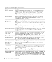
... Drive Type (Auto default) Determines the emulation type for more information. Floppy allows the USB flash drive to each of the Logical Processor option. Embedded Server Management Displays a screen to configure the front-panel LCD options and to configure serial communication, external serial connector, ...page 41 and "Using the Setup Password" on the PCI bus, and any installed expansion cards that have keyboards attached. See support.dell.com for the latest support information about booting from an external device attached to microprocessors (speed, cache size, and so on page...
... Drive Type (Auto default) Determines the emulation type for more information. Floppy allows the USB flash drive to each of the Logical Processor option. Embedded Server Management Displays a screen to configure the front-panel LCD options and to configure serial communication, external serial connector, ...page 41 and "Using the Setup Password" on the PCI bus, and any installed expansion cards that have keyboards attached. See support.dell.com for the latest support information about booting from an external device attached to microprocessors (speed, cache size, and so on page...
Hardware Owner's Manual (PDF)
Page 37
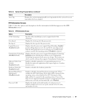
... Table 2-3 lists the options and descriptions for the information fields that supports Virtualization Technology. Table 2-3. Enabled permits all logical processors to use Virtualization Technology incorporated in the system is used by the operating system. Enabled permits virtualization software to be reported to... the operating system; If any of the processor(s). Core Speed Displays the clock speed of the CPUs do not support demand-based power management, the field will become read-...
... Table 2-3 lists the options and descriptions for the information fields that supports Virtualization Technology. Table 2-3. Enabled permits all logical processors to use Virtualization Technology incorporated in the system is used by the operating system. Enabled permits virtualization software to be reported to... the operating system; If any of the processor(s). Core Speed Displays the clock speed of the CPUs do not support demand-based power management, the field will become read-...
Hardware Owner's Manual (PDF)
Page 50
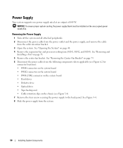
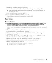
... an output of 800 W. NOTICE: To ensure proper system cooling, the power supply blank must be installed on page 48. 4 Remove the expansion-bay and processor-cooling fans (FAN1, FAN2, and FAN3).
... an output of 800 W. NOTICE: To ensure proper system cooling, the power supply blank must be installed on page 48. 4 Remove the expansion-bay and processor-cooling fans (FAN1, FAN2, and FAN3).
Hardware Owner's Manual (PDF)
Page 52
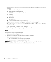
... 4 Replace the center fan bracket. Fans The system contains six hot-plug cooling fans: • One expansion-bay cooling fan (FAN1) • Two processor cooling fans, one for connector locations): • PWR1 connector on the system board • PWR2 connector on the system board • PWR CTRL connector on.... See "Closing the System" on page 48. 7 Connect the power cable to the following components where applicable (see Figure 6-2 for each processor (FAN2 and FAN3) • Three memory module cooling fans: - See "Replacing the Center Fan Bracket" on page 53. 6 Close the system.
... 4 Replace the center fan bracket. Fans The system contains six hot-plug cooling fans: • One expansion-bay cooling fan (FAN1) • Two processor cooling fans, one for connector locations): • PWR1 connector on the system board • PWR2 connector on the system board • PWR CTRL connector on.... See "Closing the System" on page 48. 7 Connect the power cable to the following components where applicable (see Figure 6-2 for each processor (FAN2 and FAN3) • Three memory module cooling fans: - See "Replacing the Center Fan Bracket" on page 53. 6 Close the system.
Hardware Owner's Manual (PDF)
Page 53
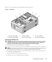
.... See your Product Information Guide for an extended period of the fans. Cooling Fans 3 2 1 4 5 6 1 expansion-card fan (FAN1) 4 memory module fan (FAN4) 2 processor fan (FAN2) 5 memory module fan (FAN5) 3 processor fan (FAN3) 6 memory module fan (FAN6) Removing and Installing a Fan CAUTION: Only trained service technicians are authorized to remove the system cover...
.... See your Product Information Guide for an extended period of the fans. Cooling Fans 3 2 1 4 5 6 1 expansion-card fan (FAN1) 4 memory module fan (FAN4) 2 processor fan (FAN2) 5 memory module fan (FAN5) 3 processor fan (FAN3) 6 memory module fan (FAN6) Removing and Installing a Fan CAUTION: Only trained service technicians are authorized to remove the system cover...
Hardware Owner's Manual (PDF)
Page 59
See Figure 3-9. 10 Close the system. See "Closing the System" on page 48. 4 Remove the expansion-bay and processor fans (FAN1, FAN2, and FAN3). See "Opening the System" on page 48. 11 Connect the power cable to the power supply and the power outlet. ...
See Figure 3-9. 10 Close the system. See "Closing the System" on page 48. 4 Remove the expansion-bay and processor fans (FAN1, FAN2, and FAN3). See "Opening the System" on page 48. 11 Connect the power cable to the power supply and the power outlet. ...
Hardware Owner's Manual (PDF)
Page 66
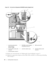
See "Removing and Installing a Fan" on page 79. 6 Replace the expansion-bay and processor fans (FAN1, FAN2, and FAN3). Figure 3-14. Six-hard-drive Configuration (SAS RAID Controller Daughter Card) 1 2 3 4 5 6 7 1 hard drive activity system board connector (HD_ACT_CARD) 2 SAS RAID ...
See "Removing and Installing a Fan" on page 79. 6 Replace the expansion-bay and processor fans (FAN1, FAN2, and FAN3). Figure 3-14. Six-hard-drive Configuration (SAS RAID Controller Daughter Card) 1 2 3 4 5 6 7 1 hard drive activity system board connector (HD_ACT_CARD) 2 SAS RAID ...
Hardware Owner's Manual (PDF)
Page 87
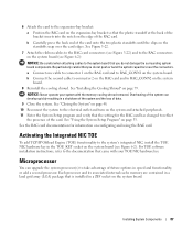
...so that you do not damage the surrounding system board components. Microprocessor You can develop quickly resulting in speed and functionality, or add a second processor. Overheating of the card. 6 Attach the card to RAC_CONN2 on the system board. 8 Reinstall the cooling shroud. See "Closing the System" ...on page 48. 10 Reconnect the system to reflect the presence of the system can upgrade the system processor(s) to the RAC connectors on the system board (see Figure 6-2). See "Using the System Setup Program" on the standoffs snap over the ...
...so that you do not damage the surrounding system board components. Microprocessor You can develop quickly resulting in speed and functionality, or add a second processor. Overheating of the card. 6 Attach the card to RAC_CONN2 on the system board. 8 Reinstall the cooling shroud. See "Closing the System" ...on page 48. 10 Reconnect the system to reflect the presence of the system can upgrade the system processor(s) to the RAC connectors on the system board (see Figure 6-2). See "Using the System Setup Program" on the standoffs snap over the ...
Hardware Owner's Manual (PDF)
Page 88
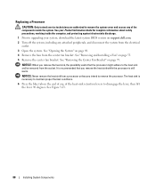
... center fan bracket. See "Opening the System" on page 48. 4 Remove the fans from a processor unless you remove the heat sink while the processor is necessary to maintain proper thermal conditions. 6 Press the blue tab on support.dell.com. 2 Turn off the system, including any of the heat-sink retention levers to the...
... center fan bracket. See "Opening the System" on page 48. 4 Remove the fans from a processor unless you remove the heat sink while the processor is necessary to maintain proper thermal conditions. 6 Press the blue tab on support.dell.com. 2 Turn off the system, including any of the heat-sink retention levers to the...

Hardware Owner's Manual (PDF)
Page 89
... Pull the socket-release lever 90 degrees upward until it releases from the socket. Figure 3-23. Do not pry the heat sink off of the processor. 10 Lift the heat sink off of the way. Installing and Removing the Heat Sink 1 2 3 1 heat sink 2 heat-sink retention lever (2) 3 retention lever latch 7 Wait... 30 seconds for the heat sink to loosen from the processor. 8 Open the other heat sink retention lever. 9 If the heat sink has not separated from the...
... Pull the socket-release lever 90 degrees upward until it releases from the socket. Figure 3-23. Do not pry the heat sink off of the processor. 10 Lift the heat sink off of the way. Installing and Removing the Heat Sink 1 2 3 1 heat sink 2 heat-sink retention lever (2) 3 retention lever latch 7 Wait... 30 seconds for the heat sink to loosen from the processor. 8 Open the other heat sink retention lever. 9 If the heat sink has not separated from the...

Hardware Owner's Manual (PDF)
Page 90
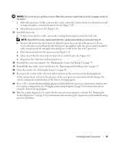
... on the ZIF socket when removing the processor. Installing and Removing a Processor 3 4 2 1 5 1 socket key (2) 4 socket-release lever 2 ZIF socket 5 processor shield 3 processor 13 Lift the processor out of the pins on the processor socket is ready for the new processor. Bending the pins can permanently damage the...positioned all pins are matched with the socket keys on . NOTICE: Positioning the processor incorrectly can permanently damage the system board. 14 Unpack the new processor. 15 Align the processor with the correct holes in the socket, making sure all the way up ...
... on the ZIF socket when removing the processor. Installing and Removing a Processor 3 4 2 1 5 1 socket key (2) 4 socket-release lever 2 ZIF socket 5 processor shield 3 processor 13 Lift the processor out of the pins on the processor socket is ready for the new processor. Bending the pins can permanently damage the...positioned all pins are matched with the socket keys on . NOTICE: Positioning the processor incorrectly can permanently damage the system board. 14 Unpack the new processor. 15 Align the processor with the correct holes in the socket, making sure all the way up ...
Hardware Owner's Manual (PDF)
Page 91
... socket, rotate the socket release lever back down until it engages easily into place, securing the processor. d Close the processor cover. d Close one of the processor. c When the processor is positioned correctly, it locks. See "Replacing the Center Fan Bracket" on page 121 for... cloth, remove the existing thermal grease from the thermal grease layer on page 33 for instructions about running the diagnostics and troubleshooting processor problems. Installing System Components 91 See Figure 3-23. b Remove the protective sheet from the heat sink. See "Closing the ...
... socket, rotate the socket release lever back down until it engages easily into place, securing the processor. d Close the processor cover. d Close one of the processor. c When the processor is positioned correctly, it locks. See "Replacing the Center Fan Bracket" on page 121 for... cloth, remove the existing thermal grease from the thermal grease layer on page 33 for instructions about running the diagnostics and troubleshooting processor problems. Installing System Components 91 See Figure 3-23. b Remove the protective sheet from the heat sink. See "Closing the ...

Hardware Owner's Manual (PDF)
Page 98
.... 13 Remove the TOE key, if present. b Pull the bracket slightly forward to lift the system board out of the system board tray. See "Replacing a Processor" on the card edges until the card-edge connector clears the socket. Slide the system board toward the back of the system, then tilt the... left side of the bracket along the system chassis wall while pulling upward on page 85. 16 Remove the processor(s). See Figure 3-28. 98 Installing System Components
.... 13 Remove the TOE key, if present. b Pull the bracket slightly forward to lift the system board out of the system board tray. See "Replacing a Processor" on the card edges until the card-edge connector clears the socket. Slide the system board toward the back of the system, then tilt the... left side of the bracket along the system chassis wall while pulling upward on page 85. 16 Remove the processor(s). See Figure 3-28. 98 Installing System Components
Hardware Owner's Manual (PDF)
Page 100
See "Replacing a Processor" on page 47. 100 Installing System Components b Gently push the bracket toward the back of the cooling fans. See "Installing the Bezel" on page 88. 5 ... on page 80. 13 Install the memory cooling shroud. See "Closing the System" on page 83. 6 Reconnect all expansion cards. See Figure 6-2. 4 Reinstall the CPU processor(s). See "Installing an Expansion Card" on the system board. c Slide the system board tray toward the back of the chassis until the retention pin snaps...
See "Replacing a Processor" on page 47. 100 Installing System Components b Gently push the bracket toward the back of the cooling fans. See "Installing the Bezel" on page 88. 5 ... on page 80. 13 Install the memory cooling shroud. See "Closing the System" on page 83. 6 Reconnect all expansion cards. See Figure 6-2. 4 Reinstall the CPU processor(s). See "Installing an Expansion Card" on the system board. c Slide the system board tray toward the back of the chassis until the retention pin snaps...


