User Manual
Page 24
... What Is the ACL Redirect Function 541 What Is the ACL Mirror Function 541 What Is ACL Logging 542 What Are Time-Based ACLs 542 24 Contents
... What Is the ACL Redirect Function 541 What Is the ACL Mirror Function 541 What Is ACL Logging 542 What Are Time-Based ACLs 542 24 Contents
User Manual
Page 29
24 Configuring Port-Based Traffic Control 687 Port-Based Traffic Control Overview 687 What is Flow Control 688 What is Storm Control 688 What are Protected ...
24 Configuring Port-Based Traffic Control 687 Port-Based Traffic Control Overview 687 What is Flow Control 688 What is Storm Control 688 What are Protected ...

User Manual
Page 81
...PowerConnect 7024 with 24 10/100/1000Base-T Ports 10/100/1000Base-T Auto-sensing Combo Ports Full Duplex RJ-45 Ports Hardware Overview 81 The topics covered in the PowerConnect 7000 Series. 3 Hardware Overview This section provides an overview of the switch models in this section include: • PowerConnect 7000 Series Front Panel • PowerConnect... 7000 Series Back Panel • LED Definitions PowerConnect 7000 Series Front Panel The PowerConnect 7000 Series front panel includes the ...
...PowerConnect 7024 with 24 10/100/1000Base-T Ports 10/100/1000Base-T Auto-sensing Combo Ports Full Duplex RJ-45 Ports Hardware Overview 81 The topics covered in the PowerConnect 7000 Series. 3 Hardware Overview This section provides an overview of the switch models in this section include: • PowerConnect 7000 Series Front Panel • PowerConnect... 7000 Series Back Panel • LED Definitions PowerConnect 7000 Series Front Panel The PowerConnect 7000 Series front panel includes the ...

User Manual
Page 82
PowerConnect 7048 with 24 SFP Ports Combo Ports SFP Ports Figure 3-4. PowerConnect 7024F with 48 10/100/1000Base-T Ports Combo Ports 10/100/1000Base-T Auto-sensing Full Duplex RJ-45 Ports Combo Ports 82 Hardware Overview Figure 3-2. PowerConnect 7024P with 24 10/100/1000Base-T PoE Plus Ports 10/100/1000Base-T RJ-45 PoE Plus Ports Providing up to 30W per Port Figure 3-3.
PowerConnect 7048 with 24 SFP Ports Combo Ports SFP Ports Figure 3-4. PowerConnect 7024F with 48 10/100/1000Base-T Ports Combo Ports 10/100/1000Base-T Auto-sensing Full Duplex RJ-45 Ports Combo Ports 82 Hardware Overview Figure 3-2. PowerConnect 7024P with 24 10/100/1000Base-T PoE Plus Ports 10/100/1000Base-T RJ-45 PoE Plus Ports Providing up to 30W per Port Figure 3-3.
User Manual
Page 84
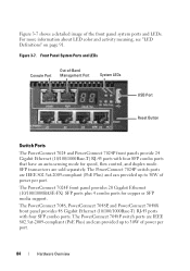
...Overview Figure 3-7. The PowerConnect 7024P switch ports are IEEE 802.3at-2009-compliant (PoE Plus) and can provided up to 30W of -Band Management Port System LEDs USB Port Reset Button Switch Ports The PowerConnect 7024 and PowerConnect 7024P front panels provide 24 Gigabit Ethernet (10/...100/1000Base-T) RJ-45 ports with four SFP combo ports. The PowerConnect 7024F front panel provides 20 Gigabit Ethernet (10/100/1000BASE-FX) ...
...Overview Figure 3-7. The PowerConnect 7024P switch ports are IEEE 802.3at-2009-compliant (PoE Plus) and can provided up to 30W of -Band Management Port System LEDs USB Port Reset Button Switch Ports The PowerConnect 7024 and PowerConnect 7024P front panels provide 24 Gigabit Ethernet (10/...100/1000Base-T) RJ-45 ports with four SFP combo ports. The PowerConnect 7024F front panel provides 20 Gigabit Ethernet (10/100/1000BASE-FX) ...
User Manual
Page 90
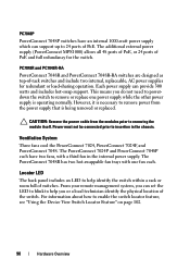
...two hot-swappable fan trays with a third fan in the chassis. Ventilation System Three fans cool the PowerConnect 7024, PowerConnect 7024F, and PowerConnect 7048. The PowerConnect 7024P and PowerConnect 7048P each have an internal 1000-watt power supply which can provide 300 watts and includes hot-swap ... itself. For information about how to insertion in the internal power supply. The additional external power supply (PowerConnect MPS1000) allows all 48 ports of PoE, or 24 ports of -rack switches and include two internal, replaceable, AC power supplies for the switch. However,...
...two hot-swappable fan trays with a third fan in the chassis. Ventilation System Three fans cool the PowerConnect 7024, PowerConnect 7024F, and PowerConnect 7048. The PowerConnect 7024P and PowerConnect 7048P each have an internal 1000-watt power supply which can provide 300 watts and includes hot-swap ... itself. For information about how to insertion in the internal power supply. The additional external power supply (PowerConnect MPS1000) allows all 48 ports of PoE, or 24 ports of -rack switches and include two internal, replaceable, AC power supplies for the switch. However,...
User Manual
Page 181
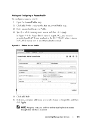
... Management Access 181 NOTE: Assigning an access profile to the profile, and then click Apply. Access on VLAN 1 from a host in the 10.27.65.0/24 subnet. Adding and Configuring an Access Profile To configure an access profile: 1 Open the Access Profile page. 2 Click Add Profile to display the Add an...
... Management Access 181 NOTE: Assigning an access profile to the profile, and then click Apply. Access on VLAN 1 from a host in the 10.27.65.0/24 subnet. Adding and Configuring an Access Profile To configure an access profile: 1 Open the Access Profile page. 2 Click Add Profile to display the Add an...
User Manual
Page 182
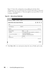
Figure 9-5 shows the configuration of VLAN 1. Add an Access Profile Rule 7 Click Show All to Port 1. Figure 9-5. This rule might be necessary if Port 1 is not a member of an additional rule that allows management access to a host in the 10.27.65.0/24 subnet that is 2. The rule priority is connected to view information about the Access Profile and its rules. 182 Controlling Management Access
Figure 9-5 shows the configuration of VLAN 1. Add an Access Profile Rule 7 Click Show All to Port 1. Figure 9-5. This rule might be necessary if Port 1 is not a member of an additional rule that allows management access to a host in the 10.27.65.0/24 subnet that is 2. The rule priority is connected to view information about the Access Profile and its rules. 182 Controlling Management Access
User Manual
Page 199
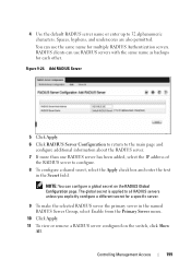
... unless you explicitly configure a different secret for each other. Controlling Management Access 199 You can configure a global secret on the switch, click Show All. Figure 9-24. Add RADIUS Server 5 Click Apply. 6 Click RADIUS Server Configuration to return to the main page and configure additional information about the RADIUS server. 7 If more...
... unless you explicitly configure a different secret for each other. Controlling Management Access 199 You can configure a global secret on the switch, click Show All. Figure 9-24. Add RADIUS Server 5 Click Apply. 6 Click RADIUS Server Configuration to return to the main page and configure additional information about the RADIUS server. 7 If more...

User Manual
Page 258
Figure 10-24. Email Alert Statistics 258 Monitoring and Logging System Information To display the Email Alert Statistics page, click System → Email Alerts → Email Alert Statistics in the navigation panel. Email Alert Statistics Use the Email Alert Statistics page to view the number of emails that were successfully and unsuccessfully sent, and when emails were sent.
Figure 10-24. Email Alert Statistics 258 Monitoring and Logging System Information To display the Email Alert Statistics page, click System → Email Alerts → Email Alert Statistics in the navigation panel. Email Alert Statistics Use the Email Alert Statistics page to view the number of emails that were successfully and unsuccessfully sent, and when emails were sent.

User Manual
Page 303
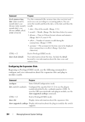
... Date Manually Beginning in hours and minutes. (Range: hh: 0-23, mm: 0-59) • offset - Day of the month. (Range: 1-5, first, last) • day - Time in 24-hour format in Privileged EXEC mode, use the usa or eu keywords to add during the summertime. (Range:1-1440) • acronym - Minutes difference from UTC... then the date, or the date and then the time. {hh:mm:ss mm/dd/yyyy • hh:mm:ss -Time in hours (24-hour format, from 01-24), minutes (00-59), and seconds (00-59). • mm/dd/yyyy - Otherwise, configure the start and end times by using the following commands...
... Date Manually Beginning in hours and minutes. (Range: hh: 0-23, mm: 0-59) • offset - Day of the month. (Range: 1-5, first, last) • day - Time in 24-hour format in Privileged EXEC mode, use the usa or eu keywords to add during the summertime. (Range:1-1440) • acronym - Minutes difference from UTC... then the date, or the date and then the time. {hh:mm:ss mm/dd/yyyy • hh:mm:ss -Time in hours (24-hour format, from 01-24), minutes (00-59), and seconds (00-59). • mm/dd/yyyy - Otherwise, configure the start and end times by using the following commands...
User Manual
Page 304
.... show slot Display status information about the time zone and summer time. Month. (Range: The first three letters by the cardindex number (CID). Time in 24-hour format in modules (cards). Day of minutes to add during the summertime. (Range:1-1440) • acronym - month date} year • date- show supported cardtype...
.... show slot Display status information about the time zone and summer time. Month. (Range: The first three letters by the cardindex number (CID). Time in 24-hour format in modules (cards). Day of minutes to add during the summertime. (Range:1-1440) • acronym - month date} year • date- show supported cardtype...
User Manual
Page 310
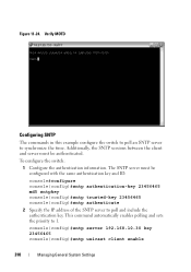
... authentication information. console(config)#sntp server 192.168.10.30 key 23456465 console(config)#sntp unicast client enable 310 Managing General System Settings Figure 11-24. Verify MOTD Configuring SNTP The commands in this example configure the switch to poll an SNTP server to synchronize the time.
... authentication information. console(config)#sntp server 192.168.10.30 key 23456465 console(config)#sntp unicast client enable 310 Managing General System Settings Figure 11-24. Verify MOTD Configuring SNTP The commands in this example configure the switch to poll an SNTP server to synchronize the time.
User Manual
Page 419
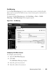
... mirroring: 1 Open the Port Mirroring page. 2 Click Add. Port Mirroring Use the Port Mirroring page to create a mirroring session in the navigation panel. Figure 15-24. Monitoring Switch Traffic 419
... mirroring: 1 Open the Port Mirroring page. 2 Click Add. Port Mirroring Use the Port Mirroring page to create a mirroring session in the navigation panel. Figure 15-24. Monitoring Switch Traffic 419
User Manual
Page 470
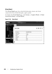
Client Detail The Client Detail page shows detailed information about each client connected to the network through a captive portal. Client Detail 470 Configuring a Captive Portal Figure 17-24. To display the Client Detail page, click System → Captive Portal → Client Connection Status → Client Detail.
Client Detail The Client Detail page shows detailed information about each client connected to the network through a captive portal. Client Detail 470 Configuring a Captive Portal Figure 17-24. To display the Client Detail page, click System → Captive Portal → Client Connection Status → Client Detail.
User Manual
Page 503
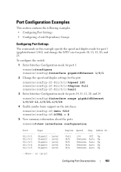
console(config)#interface range gigabitEthernet 1/0/10-12,1/0/20,1/0/24 4 Enable jumbo frame support on the interfaces. Full 100 Off Up N/A Unknown Auto Up N/A Unknown Auto Up N/A Unknown Auto Up N/A Unknown Auto Up Configuring Port ... commands in this example specify the speed and duplex mode for port 1 (gigabitethernet 1/0/1) and change the MTU size for ports 10, 11, 12, 20, and 24.
console(config)#interface range gigabitEthernet 1/0/10-12,1/0/20,1/0/24 4 Enable jumbo frame support on the interfaces. Full 100 Off Up N/A Unknown Auto Up N/A Unknown Auto Up N/A Unknown Auto Up N/A Unknown Auto Up Configuring Port ... commands in this example specify the speed and duplex mode for port 1 (gigabitethernet 1/0/1) and change the MTU size for ports 10, 11, 12, 20, and 24.
User Manual
Page 533
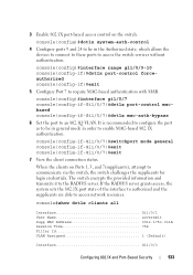
... 756 Filter Id VLAN Assigned 1 (Default) Interface Gi1/0/3 Configuring 802.1X and Port-Based Security 533 console(config)#dot1x system-auth-control 4 Configure ports 9 and 24 to be in general mode in the Authorized state, which allows the devices to connect to these ports to the RADIUS server. The switch encrypts...
... 756 Filter Id VLAN Assigned 1 (Default) Interface Gi1/0/3 Configuring 802.1X and Port-Based Security 533 console(config)#dot1x system-auth-control 4 Configure ports 9 and 24 to be in general mode in the Authorized state, which allows the devices to connect to these ports to the RADIUS server. The switch encrypts...
User Manual
Page 564
... the range. For example, 8:00 is 8:00 am and 20:00 is no start time and date are specified, the configuration statement is expressed in a 24-hour clock, in the form of the rules that are defined for the named time date] [end time date ]} range. • start time Configure a nonrecurring...
... the range. For example, 8:00 is 8:00 am and 20:00 is no start time and date are specified, the configuration statement is expressed in a 24-hour clock, in the form of the rules that are defined for the named time date] [end time date ]} range. • start time Configure a nonrecurring...
User Manual
Page 565
... form of days: Monday, Tuesday, Wednesday, Thursday, Friday, Saturday, Sunday. weekdays -- The second occurrence is the ending day(s) when the ALC rule is expressed in a 24-hour clock, in effect. Other possible values are the same as the start, they can be omitted This variable can be any single day or...
... form of days: Monday, Tuesday, Wednesday, Thursday, Friday, Saturday, Sunday. weekdays -- The second occurrence is the ending day(s) when the ALC rule is expressed in a 24-hour clock, in effect. Other possible values are the same as the start, they can be omitted This variable can be any single day or...
User Manual
Page 566
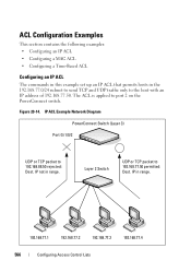
.... ` ` ` 192.168.77.1 192.168.77.2 192.168.77.3 ` 192.168.77.4 566 Configuring Access Control Lists IP in range. IP ACL Example Network Diagram PowerConnect Switch (Layer 3) Port Gi 1/0/2 UDP or TCP packet to 192.168.77.50 permitted: Dest. ACL Configuration Examples This section contains the following examples: •... an IP ACL The commands in this example set up an IP ACL that permits hosts in the 192.168.77.0/24 subnet to send TCP and UDP traffic only to port 2 on the PowerConnect switch. The ACL is applied to the host with an IP address of 192.168.77.50.
.... ` ` ` 192.168.77.1 192.168.77.2 192.168.77.3 ` 192.168.77.4 566 Configuring Access Control Lists IP in range. IP ACL Example Network Diagram PowerConnect Switch (Layer 3) Port Gi 1/0/2 UDP or TCP packet to 192.168.77.50 permitted: Dest. ACL Configuration Examples This section contains the following examples: •... an IP ACL The commands in this example set up an IP ACL that permits hosts in the 192.168.77.0/24 subnet to send TCP and UDP traffic only to port 2 on the PowerConnect switch. The ACL is applied to the host with an IP address of 192.168.77.50.