Command Line Interface (CLI) Guide (.htm)
Page 275
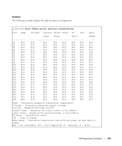
... N/A N/A g17 N/A N/A N/A N/A N/A N/A N/A g18 N/A N/A N/A N/A N/A N/A N/A g19 N/A N/A N/A N/A N/A N/A N/A g20 N/A N/A N/A N/A N/A N/A N/A g21 N/A N/A N/A N/A N/A N/A N/A g22 N/A N/A N/A N/A N/A N/A N/A g23 N/A N/A N/A N/A N/A N/A N/A g24 N/A N/A N/A N/A N/A N/A N/A ----N/A N/A N/A N/A N/A N/A N/A N/A N/A N/A N/A N/A N/A N/A N/A N/A N/A N/A N/A N/A N/A N/A N/A N/A Temp - Internally measured supply voltage Current - Measured TX bias current Output Power - Loss of signal Data Ready - Examples The following example displays the optical...
... N/A N/A g17 N/A N/A N/A N/A N/A N/A N/A g18 N/A N/A N/A N/A N/A N/A N/A g19 N/A N/A N/A N/A N/A N/A N/A g20 N/A N/A N/A N/A N/A N/A N/A g21 N/A N/A N/A N/A N/A N/A N/A g22 N/A N/A N/A N/A N/A N/A N/A g23 N/A N/A N/A N/A N/A N/A N/A g24 N/A N/A N/A N/A N/A N/A N/A ----N/A N/A N/A N/A N/A N/A N/A N/A N/A N/A N/A N/A N/A N/A N/A N/A N/A N/A N/A N/A N/A N/A N/A N/A Temp - Internally measured supply voltage Current - Measured TX bias current Output Power - Loss of signal Data Ready - Examples The following example displays the optical...
Command Line Interface (CLI) Guide (.htm)
Page 276
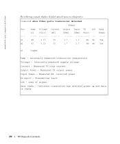
... Yes g3 Copper Temp - Internally measured supply voltage. Output Power - Tx Fault - Loss of signal Data ready - Internally measured transceiver temperature. Current - Measured RX received power. Indicates transceiver has achieved power up and data is ready. 276 PHY Diagnostics Commands Measured TX bias current. www.dell.com | support.dell.com The following example displays detailed optical...
... Yes g3 Copper Temp - Internally measured supply voltage. Output Power - Tx Fault - Loss of signal Data ready - Internally measured transceiver temperature. Current - Measured RX received power. Indicates transceiver has achieved power up and data is ready. 276 PHY Diagnostics Commands Measured TX bias current. www.dell.com | support.dell.com The following example displays detailed optical...
Command Line Interface (CLI) Guide (.htm)
Page 429
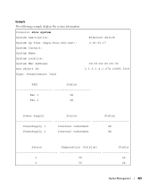
Example The following example displays the system information. Console> show system System Description: Ethernet Switch System Up Time (days,hour:min:sec): 0,00:00:17 System Contact: System Name: System Location: System MAC Address: 00:00:b0:00:00:00 Sys Object ID: 1.3.6.1.4.1.674.10895.3006 Type: PowerConnect 3424 FAN Status Fan 1 OK Fan 2 OK Power supply Source Status PowerSupply 1 Internal redundant OK PowerSupply 2 Internal redundant OK Sensor Temperature (Celsius) Status 1 38 ok 2 36 ok System Management 429
Example The following example displays the system information. Console> show system System Description: Ethernet Switch System Up Time (days,hour:min:sec): 0,00:00:17 System Contact: System Name: System Location: System MAC Address: 00:00:b0:00:00:00 Sys Object ID: 1.3.6.1.4.1.674.10895.3006 Type: PowerConnect 3424 FAN Status Fan 1 OK Fan 2 OK Power supply Source Status PowerSupply 1 Internal redundant OK PowerSupply 2 Internal redundant OK Sensor Temperature (Celsius) Status 1 38 ok 2 36 ok System Management 429
User's Guide (.htm)
Page 3
Contents 1 Introduction PowerConnect 6024 23 PowerConnect 6024F 24 CLI Documentation 24 Features 24 Port Based Features 24 MAC Address Supported Features 26 Layer 2 Features 26 VLAN Supported Features 27 Spanning Tree...Service Features 31 Device Management Features 32 Security Features 34 2 Hardware Description Ports Description 37 PowerConnect 6024 37 PowerConnect 6024F 38 Out-of-Band Management Port 38 Console (RS-232) Port 38 Hardware Components 39 Physical Dimensions 39 Power Supplies 39 Reset Button 40 Ventilation System 40 LED Definitions 40 SFP Port LEDs 41 System...
Contents 1 Introduction PowerConnect 6024 23 PowerConnect 6024F 24 CLI Documentation 24 Features 24 Port Based Features 24 MAC Address Supported Features 26 Layer 2 Features 26 VLAN Supported Features 27 Spanning Tree...Service Features 31 Device Management Features 32 Security Features 34 2 Hardware Description Ports Description 37 PowerConnect 6024 37 PowerConnect 6024F 38 Out-of-Band Management Port 38 Console (RS-232) Port 38 Hardware Components 39 Physical Dimensions 39 Power Supplies 39 Reset Button 40 Ventilation System 40 LED Definitions 40 SFP Port LEDs 41 System...
User's Guide (.htm)
Page 13
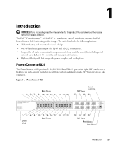
... Out of Layer 2, Layer 3+, security, and management features. • High availability with hot swappable power supplies and cooling fans PowerConnect 6024 The PowerConnect 6024 provides 24 10/100/1000 Base-T RJ-45 ports with eight SFP combo ports that extends the Dell PowerConnect LAN switching product range. The switch includes the following features: • 1U form factor, rack...
... Out of Layer 2, Layer 3+, security, and management features. • High availability with hot swappable power supplies and cooling fans PowerConnect 6024 The PowerConnect 6024 provides 24 10/100/1000 Base-T RJ-45 ports with eight SFP combo ports that extends the Dell PowerConnect LAN switching product range. The switch includes the following features: • 1U form factor, rack...
User's Guide (.htm)
Page 29
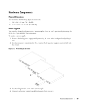
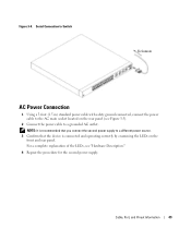
... mm (W x D x H). • 17.32 x 18.11 x 1.73 inch (W x D x H). Power Supplies Your switch is inserted fully into the slot, ensuring that the power supply is shipped with two internal power supplies. Figure 2-3. Hardware Description 39 Power Supply Insertion 1 2 3 Insert and tighten the screw to the power supply. 4 Connect each power supply to a different external power source. You can verify operation by removing its screw...
... mm (W x D x H). • 17.32 x 18.11 x 1.73 inch (W x D x H). Power Supplies Your switch is inserted fully into the slot, ensuring that the power supply is shipped with two internal power supplies. Figure 2-3. Hardware Description 39 Power Supply Insertion 1 2 3 Insert and tighten the screw to the power supply. 4 Connect each power supply to a different external power source. You can verify operation by removing its screw...
User's Guide (.htm)
Page 30
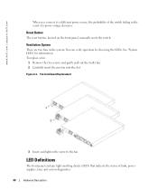
.... Reset Button The reset button, located on the front panel, manually resets the switch. Ventilation System There are two fans in the event of links, power supplies, fans, and system diagnostics. 40 Hardware Description www.dell.com | support.dell.com When you connect to the fan.
.... Reset Button The reset button, located on the front panel, manually resets the switch. Ventilation System There are two fans in the event of links, power supplies, fans, and system diagnostics. 40 Hardware Description www.dell.com | support.dell.com When you connect to the fan.
User's Guide (.htm)
Page 32
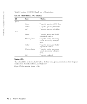
... at 10 Mbps. System LEDs The system LEDs, located on the left side of the front panel, provide information about the power supplies, fans, thermal conditions, and diagnostics. www.dell.com | support.dell.com Table 2-2 contains 10/100/1000 Base-T port LED definitions. Table 2-2. 10/100/1000 Base-T Port Definitions LED Speed Link Color...
... at 10 Mbps. System LEDs The system LEDs, located on the left side of the front panel, provide information about the power supplies, fans, thermal conditions, and diagnostics. www.dell.com | support.dell.com Table 2-2 contains 10/100/1000 Base-T port LED definitions. Table 2-2. 10/100/1000 Base-T Port Definitions LED Speed Link Color...
User's Guide (.htm)
Page 33
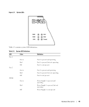
Figure 2-7. Fan 2 is present, but not operating. Fan 1 is not present. Fan 2 is not present. Power Supply 1 is present, but not operating. Hardware Description 43 System LED Definitions LED Fan 1 Fan 2 PWR1 Color Green Red Off Green Red Off Green Red Off Definition Fan 1 is not present. Fan 1 is present and operating. Fan 2 is present, but not operating. Power Supply 1 is present and operating. Table 2-3. Power Supply 1 is present and operating. System LEDs Table 2-3 contains system LED definitions.
Figure 2-7. Fan 2 is present, but not operating. Fan 1 is not present. Fan 2 is not present. Power Supply 1 is present, but not operating. Hardware Description 43 System LED Definitions LED Fan 1 Fan 2 PWR1 Color Green Red Off Green Red Off Green Red Off Definition Fan 1 is not present. Fan 1 is present and operating. Fan 2 is present, but not operating. Power Supply 1 is present and operating. Table 2-3. Power Supply 1 is present and operating. System LEDs Table 2-3 contains system LED definitions.
User's Guide (.htm)
Page 34
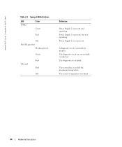
Power Supply 2 is currently in progress. The system has exceeded the maximum temperature. A diagnostics test is not present. The diagnostics test was successfully completed. The system temperature is present, but not operating. The diagnostics test failed. Power Supply 2 is normal. 44 Hardware Description System LED Definitions LED PWR2 Color Green Red Off Dia (Diagnostic) Flashing Green Green Red Thermal Red Off Definition Power Supply 2 is present and operating. www.dell.com | support.dell.com Table 2-3.
Power Supply 2 is currently in progress. The system has exceeded the maximum temperature. A diagnostics test is not present. The diagnostics test was successfully completed. The system temperature is present, but not operating. The diagnostics test failed. Power Supply 2 is normal. 44 Hardware Description System LED Definitions LED PWR2 Color Green Red Off Dia (Diagnostic) Flashing Green Green Red Thermal Red Off Definition Power Supply 2 is present and operating. www.dell.com | support.dell.com Table 2-3.
User's Guide (.htm)
Page 37
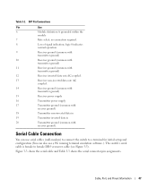
... (null-modem) to connect the switch to female DB-9 crossover cable (see Figure 3-3). AC coupled. 14 Receiver ground (common with transmitter ground) 15 Receiver power supply 16 Transmitter power supply 17 Transmitter ground (common with receiver ground) 18 Transmitter non-inverted data in 19 Transmitter inverted data in 20 Transmitter ground (common with transmitter...
... (null-modem) to connect the switch to female DB-9 crossover cable (see Figure 3-3). AC coupled. 14 Receiver ground (common with transmitter ground) 15 Receiver power supply 16 Transmitter power supply 17 Transmitter ground (common with receiver ground) 18 Transmitter non-inverted data in 19 Transmitter inverted data in 20 Transmitter ground (common with transmitter...
User's Guide (.htm)
Page 39
For a complete explanation of the LEDs, see Figure 3-5). 2 Connect the power cable to a different power source. 3 Confirm that the device is recommended that you connect the second power supply to a grounded AC outlet. NOTE: It is connected and operating correctly by examining the LEDs on the front and rear panel. Cable, Port, and Pinout ...
For a complete explanation of the LEDs, see Figure 3-5). 2 Connect the power cable to a different power source. 3 Confirm that the device is recommended that you connect the second power supply to a grounded AC outlet. NOTE: It is connected and operating correctly by examining the LEDs on the front and rear panel. Cable, Port, and Pinout ...
User's Guide (.htm)
Page 53
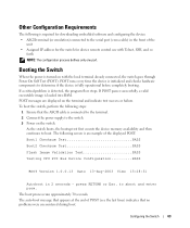
... at the end of POST (see the last lines) indicates that the ASCII cable is connected to the terminal. 2 Connect the power supply to the switch. 3 Power on the switch. to abort and enter prom. To boot the switch, perform the following steps: 1 Ensure that no problems were...the unit • Assigned IP address for the switch for device remote control use with the local terminal already connected, the switch goes through Power On Self Test (POST). Other Configuration Requirements The following is required for downloading embedded software and configuring the device: • ASCII terminal ...
... at the end of POST (see the last lines) indicates that the ASCII cable is connected to the terminal. 2 Connect the power supply to the switch. 3 Power on the switch. to abort and enter prom. To boot the switch, perform the following steps: 1 Ensure that no problems were...the unit • Assigned IP address for the switch for device remote control use with the local terminal already connected, the switch goes through Power On Self Test (POST). Other Configuration Requirements The following is required for downloading embedded software and configuring the device: • ASCII terminal ...

User's Guide (.htm)
Page 96
...viewing fields displayed on the System Health page. The fan is operating normally. - The power supply is not operating normally. System Health CLI Commands CLI Command show system Description Displays system information. 106...Power Supply-The power supply status. - The fan is currently not present. Temperature-The temperature at which the device is currently not present. Not Present-A fan is currently running. The power supply is not operating normally. Fan-Indicates the fan status. The PowerConnect 6024/6024F has two fans. - Table 6-3. www.dell.com | support.dell...
...viewing fields displayed on the System Health page. The fan is operating normally. - The power supply is not operating normally. System Health CLI Commands CLI Command show system Description Displays system information. 106...Power Supply-The power supply status. - The fan is currently not present. Temperature-The temperature at which the device is currently not present. Not Present-A fan is currently running. The power supply is not operating normally. Fan-Indicates the fan status. The PowerConnect 6024/6024F has two fans. - Table 6-3. www.dell.com | support.dell...
User's Guide (.htm)
Page 97
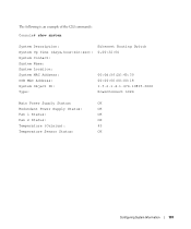
The following is an example of the CLI commands: Console# show system System Description: System Up Time (days,hour:min:sec): System Contact: System Name: System Location: System MAC Address: OOB MAC Address: System Object ID: Type: Ethernet Routing Switch 0,00:32:04 00:0d:56:2f:45:30 00:00:00:00:00:18 1.3.6.1.4.1.674.10895.3000 PowerConnect 6024 Main Power Supply Status: OK Redundant Power Supply Status: OK Fan 1 Status: OK Fan 2 Status: OK Temperature (Celsius): 45 Temperature Sensor Status: OK Configuring System Information 107
The following is an example of the CLI commands: Console# show system System Description: System Up Time (days,hour:min:sec): System Contact: System Name: System Location: System MAC Address: OOB MAC Address: System Object ID: Type: Ethernet Routing Switch 0,00:32:04 00:0d:56:2f:45:30 00:00:00:00:00:18 1.3.6.1.4.1.674.10895.3000 PowerConnect 6024 Main Power Supply Status: OK Redundant Power Supply Status: OK Fan 1 Status: OK Fan 2 Status: OK Temperature (Celsius): 45 Temperature Sensor Status: OK Configuring System Information 107
User's Guide (.htm)
Page 160
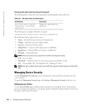
... Internally measured transceiver temperature • Voltage - Measured RX received power in the tree view. Internally measured supply voltage • Current - Not Available, N/S - Warning, E - Measured TX bias current • Output Power - Loss of the CLI command: console# show fiber-ports ...in milliwatts • TX Fault - www.dell.com | support.dell.com Performing Fiber Optic Cable Tests Using CLI Commands The following is ready • N/A - Measured TX output power in milliWatts • Input Power - Managing Device Security Use the Management ...
... Internally measured transceiver temperature • Voltage - Measured RX received power in the tree view. Internally measured supply voltage • Current - Not Available, N/S - Warning, E - Measured TX bias current • Output Power - Loss of the CLI command: console# show fiber-ports ...in milliwatts • TX Fault - www.dell.com | support.dell.com Performing Fiber Optic Cable Tests Using CLI Commands The following is ready • N/A - Measured TX output power in milliWatts • Input Power - Managing Device Security Use the Management ...


