
Command Line Interface Guide
Page 414
... System Contact: System Name: RS1 System location: System MAC Address: 00:00:b0:00:00:00 Sys Object ID: 1.3.6.1.4.1.674.10895.3020 PowerConnect 5400 Type: Main Power Supply ok Status Redundant Power ok Supply Status: Fan 1 Status: OK Fan 2 Status: OK console> set system The set system {iscsi | dva} • iscsi - Example The following example...
... System Contact: System Name: RS1 System location: System MAC Address: 00:00:b0:00:00:00 Sys Object ID: 1.3.6.1.4.1.674.10895.3020 PowerConnect 5400 Type: Main Power Supply ok Status Redundant Power ok Supply Status: Fan 1 Status: OK Fan 2 Status: OK console> set system The set system {iscsi | dva} • iscsi - Example The following example...

User's Guide
Page 3
Contents 1 Introduction 13 PowerConnect 54xx Series Systems 13 Features 14 General Features 14 MAC Address Supported Features 15 Layer 2 Features 16 VLAN Supported Features 17 Spanning Tree Protocol ...Additional CLI Documentation 23 2 Hardware Description 25 Device Port Configurations 25 PowerConnect 54xx Series Systems Front Panel Port Description 25 PowerConnect Back Panel Port Description 26 Device Ports 26 Physical Dimensions 27 LED Definitions 27 Port LEDs 27 System LEDs 28 Hardware Components 29 Power Supplies 29 Reset Button 30 Ventilation System 30 Contents 3
Contents 1 Introduction 13 PowerConnect 54xx Series Systems 13 Features 14 General Features 14 MAC Address Supported Features 15 Layer 2 Features 16 VLAN Supported Features 17 Spanning Tree Protocol ...Additional CLI Documentation 23 2 Hardware Description 25 Device Port Configurations 25 PowerConnect 54xx Series Systems Front Panel Port Description 25 PowerConnect Back Panel Port Description 26 Device Ports 26 Physical Dimensions 27 LED Definitions 27 Port LEDs 27 System LEDs 28 Hardware Components 29 Power Supplies 29 Reset Button 30 Ventilation System 30 Contents 3

User's Guide
Page 4
3 Installing the PowerConnect Device 31 Installation Precautions 31 Site Requirements 32 Unpacking 32 Package Contents 32 Unpacking the Device 32 Mounting the Device 33 Overview 33 Mounting the System 33 Installing the Device without a Rack 34 Connecting the Device 34 Connecting a Device to a Terminal 34 Connecting a Device to a Power Supply 36 Port Connections, Cables...
3 Installing the PowerConnect Device 31 Installation Precautions 31 Site Requirements 32 Unpacking 32 Package Contents 32 Unpacking the Device 32 Mounting the Device 33 Overview 33 Mounting the System 33 Installing the Device without a Rack 34 Connecting the Device 34 Connecting a Device to a Terminal 34 Connecting a Device to a Power Supply 36 Port Connections, Cables...

User's Guide
Page 26
...) to be activated automatically in the event of a combo port may be configured from 2400 bps up to either 110V or 220V power supplies. PowerConnect Back Panel Port Description The device back panel contains connectors for debugging, software download, etc. RS-232 Console Port One DB-9 connector...Back Panel On the device back panel are determined by the physical connection used at any one of the two physical connections of an AC power supply outage. Console Port Combo Ports A combo port is used on a combo port, and utilizes this information in the Figure 2-2. Port features...
...) to be activated automatically in the event of a combo port may be configured from 2400 bps up to either 110V or 220V power supplies. PowerConnect Back Panel Port Description The device back panel contains connectors for debugging, software download, etc. RS-232 Console Port One DB-9 connector...Back Panel On the device back panel are determined by the physical connection used at any one of the two physical connections of an AC power supply outage. Console Port Combo Ports A combo port is used on a combo port, and utilizes this information in the Figure 2-2. Port features...

User's Guide
Page 27
... are present, and a connector is inserted in the SFP port, the SFP port is active, unless the copper connector of the Base-T port of links, power supplies, fans, and system diagnostics. The port is indicated on the left LED and the duplex mode is linked at 1000 Mbps. The port is inserted...
... are present, and a connector is inserted in the SFP port, the SFP port is active, unless the copper connector of the Base-T port of links, power supplies, fans, and system diagnostics. The port is indicated on the left LED and the duplex mode is linked at 1000 Mbps. The port is inserted...

User's Guide
Page 28
... The port is Green. When the SFP port is connected, the Duplex LED on the left side of the front panel, provide information about the power supplies, fans, thermal conditions, and diagnostics. SFP Port LED Indications LED Color Description SFP Green Static The port is currently down. System LEDs The system LEDs...
... The port is Green. When the SFP port is connected, the Duplex LED on the left side of the front panel, provide information about the power supplies, fans, thermal conditions, and diagnostics. SFP Port LED Indications LED Color Description SFP Green Static The port is currently down. System LEDs The system LEDs...

User's Guide
Page 29
... both power supply units is not currently operating. The following table describes the system LED indications. Table 2-3. The redundant power supply is regulated through load sharing. The system temperature is required. To power up the device, only one power supply has an outage, the second power supply automatically continues providing power to an external power supply unit (DC unit). Power supply LEDs indicate the power supply...
... both power supply units is not currently operating. The following table describes the system LED indications. Table 2-3. The redundant power supply is regulated through load sharing. The system temperature is required. To power up the device, only one power supply has an outage, the second power supply automatically continues providing power to an external power supply unit (DC unit). Power supply LEDs indicate the power supply...

User's Guide
Page 30
...reset button, located on page 27. 30 Hardware Description AC Power Supply Unit The AC power supply unit converts standard 220/110V AC 50/60 Hz to a different power source, the probability of failure in the event of a power outage decreases. Ventilation System The device uses a fan system for... cooling. The unit automatically senses the available voltage rating (110 or 220V) and no setting is used . DC Power Supply Unit An external DC power supply unit is required. No configuration is a faulty fan. Fan operational status can be verified by observing the LEDs that indicate...
...reset button, located on page 27. 30 Hardware Description AC Power Supply Unit The AC power supply unit converts standard 220/110V AC 50/60 Hz to a different power source, the probability of failure in the event of a power outage decreases. Ventilation System The device uses a fan system for... cooling. The unit automatically senses the available voltage rating (110 or 220V) and no setting is used . DC Power Supply Unit An external DC power supply unit is required. No configuration is a faulty fan. Fan operational status can be verified by observing the LEDs that indicate...

User's Guide
Page 32
... unpacking the device, inspect the package and report any damage immediately. 32 Installing the PowerConnect Device Unpacking Package Contents While unpacking the device, ensure that the power supply is routed to 90%, non-condensing. Cabling is correctly installed. • Power - Report any evidence of damage immediately. The ambient unit operating temperature range is recommended...
... unpacking the device, inspect the package and report any damage immediately. 32 Installing the PowerConnect Device Unpacking Package Contents While unpacking the device, ensure that the power supply is routed to 90%, non-condensing. Cabling is correctly installed. • Power - Report any evidence of damage immediately. The ambient unit operating temperature range is recommended...

User's Guide
Page 33
Mounting the Device Overview The power connectors for the rack-mounting bracket on the other side of the device. WARNING: When mounting multiple devices into the rack mounting holes and tighten .... Figure 3-1. The UPS DC connector is recommended. Connection Rack Mounting Brackets 2 Insert the supplied screws into a rack, mount the devices from the unit before mounting the device in a rack or cabinet. Installing the PowerConnect Device 33 Connecting a DC Redundant Power Supply (UPS) is optional, but is located on the back panel of the device...
Mounting the Device Overview The power connectors for the rack-mounting bracket on the other side of the device. WARNING: When mounting multiple devices into the rack mounting holes and tighten .... Figure 3-1. The UPS DC connector is recommended. Connection Rack Mounting Brackets 2 Insert the supplied screws into a rack, mount the devices from the unit before mounting the device in a rack or cabinet. Installing the PowerConnect Device 33 Connecting a DC Redundant Power Supply (UPS) is optional, but is located on the back panel of the device...

User's Guide
Page 36
... the PowerConnect Device Figure 3-3. Copper Cable and Optical Transceiver Diagnostics are supported. To establish a link for 10/100/1000BaseT Ports The 10/100/1000BaseT ports are summarized in Ports, Connectors, and Cables. Connecting a Device to a Power Supply 1 Using a 5-foot (1.5 m) standard power cable ...with safety ground connected, connect the power cable to the AC connector located on the back panel. 2 Connect the power cable to Rx, a link is connected and operating ...
... the PowerConnect Device Figure 3-3. Copper Cable and Optical Transceiver Diagnostics are supported. To establish a link for 10/100/1000BaseT Ports The 10/100/1000BaseT ports are summarized in Ports, Connectors, and Cables. Connecting a Device to a Power Supply 1 Using a 5-foot (1.5 m) standard power cable ...with safety ground connected, connect the power cable to the AC connector located on the back panel. 2 Connect the power cable to Rx, a link is connected and operating ...

User's Guide
Page 40
...no parity. 4 Set flow control to www.microsoft.com for information on the AC power receptacle. POST messages are displayed on SW emulation are configured correctly. 2 Connect the power supply to a Power Supply" on page 36. 5 Switch on Windows 2000 service packs. Booting the Device NOTE...: The assumed bootup information is not configured with the local terminal already connected, the device goes through Power On Self Test (POST). ...
...no parity. 4 Set flow control to www.microsoft.com for information on the AC power receptacle. POST messages are displayed on SW emulation are configured correctly. 2 Connect the power supply to a Power Supply" on page 36. 5 Switch on Windows 2000 service packs. Booting the Device NOTE...: The assumed bootup information is not configured with the local terminal already connected, the device goes through Power On Self Test (POST). ...
User's Guide
Page 70
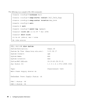
The following is an example of the CLI commands: Console (config)# hostname dell Console (config)# snmp-server contact Dell_Tech_Supp Console (config)# snmp-server location New_York Console (config)# exit Console # exit Console (config)# asset-tag 1qwepot Console> ... source DELL Switch# show system System Description: System Up Time (days,hour:min:sec): System Contact: System Name: System Location: System MAC Address: Sys Object ID: Kenan 24 0,00:04:17 spk RS1 R&D 00:10:b5:f4:00:01 1.3.6.1.4.1.674.10895.3000 Type: Main Power Supply Status ok PowerConnect 5400 Redundant Power Supply Status:...
The following is an example of the CLI commands: Console (config)# hostname dell Console (config)# snmp-server contact Dell_Tech_Supp Console (config)# snmp-server location New_York Console (config)# exit Console # exit Console (config)# asset-tag 1qwepot Console> ... source DELL Switch# show system System Description: System Up Time (days,hour:min:sec): System Contact: System Name: System Location: System MAC Address: Sys Object ID: Kenan 24 0,00:04:17 spk RS1 R&D 00:10:b5:f4:00:01 1.3.6.1.4.1.674.10895.3000 Type: Main Power Supply Status ok PowerConnect 5400 Redundant Power Supply Status:...

User's Guide
Page 77
... The device fan status. The fans are not present for the specified unit - - Configuring System Information 77 The power supply is not operating normally for viewing fields displayed in the tree view. The fans are not operating normally for the specified... for the specified unit. - Viewing System Health Information The System Health page shows physical device hardware information. System Health • Power Supply Status - The main power supply is not present for the specified unit. - - To open the System Health page, click System→ General→ Health ...
... The device fan status. The fans are not present for the specified unit - - Configuring System Information 77 The power supply is not operating normally for viewing fields displayed in the tree view. The fans are not operating normally for the specified... for the specified unit. - Viewing System Health Information The System Health page shows physical device hardware information. System Health • Power Supply Status - The main power supply is not present for the specified unit. - - To open the System Health page, click System→ General→ Health ...
User's Guide
Page 78
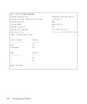
DELL Switch# show system System Description: System Up Time (days,hour:min:sec): System Contact: System Name: System Location: System MAC Address: Sys Object ID: Type: PowerConnect 5400 Power Supply Main Redundant Status -------OK OK FAN 1 2 Status -------OK OK DELL Switch# Ethernet Routing Switch 0,00:04:17 spk DELL Switch R&D 00:10:b5:f4:00:01 1.3.6.1.4.1.674.10895.3000 78 Configuring System Information
DELL Switch# show system System Description: System Up Time (days,hour:min:sec): System Contact: System Name: System Location: System MAC Address: Sys Object ID: Type: PowerConnect 5400 Power Supply Main Redundant Status -------OK OK FAN 1 2 Status -------OK OK DELL Switch# Ethernet Routing Switch 0,00:04:17 spk DELL Switch R&D 00:10:b5:f4:00:01 1.3.6.1.4.1.674.10895.3000 78 Configuring System Information
User's Guide
Page 443
... P Package Contents, 32 Package contents, 32 Passwords, 62, 171 PDU, 437 PING, 438 Port, 26 Port aggregation, 351 Port LEDs, 27 Ports, 60, 278, 405 Power supplies, 29 PPP, 438 Profiles, 147 Protocol, 337 PVID, 331, 334 Q QinQ, 323 QoS, 411, 414, 416, 438 Quality of Service, 411, 438 Queue, 419 R RADIUS...
... P Package Contents, 32 Package contents, 32 Passwords, 62, 171 PDU, 437 PING, 438 Port, 26 Port aggregation, 351 Port LEDs, 27 Ports, 60, 278, 405 Power supplies, 29 PPP, 438 Profiles, 147 Protocol, 337 PVID, 331, 334 Q QinQ, 323 QoS, 411, 414, 416, 438 Quality of Service, 411, 438 Queue, 419 R RADIUS...

Getting Started Guide
Page 5
Contents 1 Installation Overview 5 Site Preparation 5 Site Requirements 5 Unpacking 6 Package Contents 6 Unpacking the Device 6 2 Mounting the Device Overview 7 Device Rack Installation 7 Installing on a Flat Surface 8 Installing on a Wall 8 Connecting a Device to a Power Supply 9 3 Starting and Configuring the Device Connecting the Terminal to the Device 11 Booting the Switch 13 Initial Configuration 13 Contents 3
Contents 1 Installation Overview 5 Site Preparation 5 Site Requirements 5 Unpacking 6 Package Contents 6 Unpacking the Device 6 2 Mounting the Device Overview 7 Device Rack Installation 7 Installing on a Flat Surface 8 Installing on a Wall 8 Connecting a Device to a Power Supply 9 3 Starting and Configuring the Device Connecting the Terminal to the Device 11 Booting the Switch 13 Initial Configuration 13 Contents 3
Getting Started Guide
Page 7
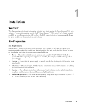
... 5 Installation Overview This document provides basic information to 113ºF) at www.support.dell.com for operator access. The ambient unit operating temperature range is preferred that two separate power supplies are lit. • Clearance - For more information, see the Dell™ PowerConnect™ 5400 series User's Guide, which is installed near an easily accessible...
... 5 Installation Overview This document provides basic information to 113ºF) at www.support.dell.com for operator access. The ambient unit operating temperature range is preferred that two separate power supplies are lit. • Clearance - For more information, see the Dell™ PowerConnect™ 5400 series User's Guide, which is installed near an easily accessible...

Getting Started Guide
Page 9
... mount the brackets. CAUTION: Disconnect all cables from the bottom up. 1 Place the supplied rack-mounting bracket on one side of the device ensuring the mounting holes on the device line up to the PowerConnect 5400 series switches. The power connectors for the device is positioned on the rack mounting bracket. Figure 2-1. CAUTION...
... mount the brackets. CAUTION: Disconnect all cables from the bottom up. 1 Place the supplied rack-mounting bracket on one side of the device ensuring the mounting holes on the device line up to the PowerConnect 5400 series switches. The power connectors for the device is positioned on the rack mounting bracket. Figure 2-1. CAUTION...

Getting Started Guide
Page 11
Mounting the Device 9 Bracket Installation for Wall Mounting Connecting a Device to a Power Supply 1 Using the supplied AC power cable, connect the power cable to the AC connector located on the back panel. 2 Do not connect the power cable to a power source in the steps detailed in Starting and Configuring the Device. Figure 2-2. Connect the device to a grounded AC outlet at this time.
Mounting the Device 9 Bracket Installation for Wall Mounting Connecting a Device to a Power Supply 1 Using the supplied AC power cable, connect the power cable to the AC connector located on the back panel. 2 Do not connect the power cable to a power source in the steps detailed in Starting and Configuring the Device. Figure 2-2. Connect the device to a grounded AC outlet at this time.


