
Command Line Interface Guide
Page 150
Default settings: Service tag: service tag 0 SW version 1.0.0.1 (date Aug 9 2007 time 10:06:42) Fast Ethernet Ports no shutdown speed 100 duplex full negotiation flow-control off mdix auto no back-pressure Gigabit Ethernet Ports no shutdown speed 1000 duplex full negotiation flow-control off mdix auto no back-pressure console# show startup-config The show startup-config Privileged EXEC mode command displays the contents of the startup configuration file. 150 Configuration and Image Files
Default settings: Service tag: service tag 0 SW version 1.0.0.1 (date Aug 9 2007 time 10:06:42) Fast Ethernet Ports no shutdown speed 100 duplex full negotiation flow-control off mdix auto no back-pressure Gigabit Ethernet Ports no shutdown speed 1000 duplex full negotiation flow-control off mdix auto no back-pressure console# show startup-config The show startup-config Privileged EXEC mode command displays the contents of the startup configuration file. 150 Configuration and Image Files

Command Line Interface Guide
Page 362
... configuration. User Guidelines The path cost method is determined by port speed and path cost method (long or short) as shown below: Interface Port-channel Gigabit Ethernet (1000 Mbps) Fast Ethernet (100 Mbps) Ethernet (10 Mbps) Long 20,000 20,000 200,000 2,000,000 Short 4 4 19 100 Command Mode Interface...
... configuration. User Guidelines The path cost method is determined by port speed and path cost method (long or short) as shown below: Interface Port-channel Gigabit Ethernet (1000 Mbps) Fast Ethernet (100 Mbps) Ethernet (10 Mbps) Long 20,000 20,000 200,000 2,000,000 Short 4 4 19 100 Command Mode Interface...

Command Line Interface Guide
Page 369
... Global Configuration mode command enables configuring an MST region by port speed and path cost method (long or short) as shown below: Interface Port-channel Gigabit Ethernet (1000 Mbps) Fast Ethernet (100 Mbps) Ethernet (10 Mbps) Long 20,000 20,000 200,000 2,000,000 Short 4 4 19 100 Command Mode Interface...
... Global Configuration mode command enables configuring an MST region by port speed and path cost method (long or short) as shown below: Interface Port-channel Gigabit Ethernet (1000 Mbps) Fast Ethernet (100 Mbps) Ethernet (10 Mbps) Long 20,000 20,000 200,000 2,000,000 Short 4 4 19 100 Command Mode Interface...

User's Guide
Page 4
... The back panel contains an RPS connector, console port, and power connector 28 PowerConnect 3548 Port Description 28 SFP Ports 29 RS-232 Console Port 29 Physical Dimensions 30 LED Definitions 30 Gigabit Port LEDs 32 System LEDs 33 Power Supplies 35 Stack ID Button 36 Reset... Button 37 Ventilation System 37 3 Installing the PowerConnect 3524/P and PowerConnect 3548/P 39 Site Preparation 39 Unpacking 39 Package Contents 39 Unpacking...
... The back panel contains an RPS connector, console port, and power connector 28 PowerConnect 3548 Port Description 28 SFP Ports 29 RS-232 Console Port 29 Physical Dimensions 30 LED Definitions 30 Gigabit Port LEDs 32 System LEDs 33 Power Supplies 35 Stack ID Button 36 Reset... Button 37 Ventilation System 37 3 Installing the PowerConnect 3524/P and PowerConnect 3548/P 39 Site Preparation 39 Unpacking 39 Package Contents 39 Unpacking...
User's Guide
Page 27
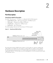
...- Ports G3 - RJ-45 ports designated as 1000Base-X SFP ports • 2 Gigabit ports - The upper row of ports is marked with odd numbers 1-23, and the lower row of ports is configured with even numbers 2-24. PowerConnect 3524 Front Panel 10/100 Base-T Ports 1, 3, 5, 7, ...23 System LEDs Reset.... Designated as stacking ports, or used as 1000Base-T ports • Console port - Hardware Description 27 Hardware Description Port Description PowerConnect 3524 Port Description The Dell™ PowerConnect™ 3524 device is marked with the following figure illustrates the...
...- Ports G3 - RJ-45 ports designated as 1000Base-X SFP ports • 2 Gigabit ports - The upper row of ports is marked with odd numbers 1-23, and the lower row of ports is configured with even numbers 2-24. PowerConnect 3524 Front Panel 10/100 Base-T Ports 1, 3, 5, 7, ...23 System LEDs Reset.... Designated as stacking ports, or used as 1000Base-T ports • Console port - Hardware Description 27 Hardware Description Port Description PowerConnect 3524 Port Description The Dell™ PowerConnect™ 3524 device is marked with the following figure illustrates the...
User's Guide
Page 28
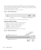
...figure illustrates the PowerConnect 3548 front panel. PowerConnect 3548 Port Description The PowerConnect 3548 device is used to manually reset the device. RS-232 Console based port The following ports: • 48 FE ports - RJ-45 ports designated as 1000Base-X SFP ports • 2 Gigabit ports - Figure... button does not extend beyond the unit's front panel surface, so reset by pressing it accidentally is used to select the unit number. PowerConnect 3548 Front Panel 10/100 Base-T Ports 1, 3, 5, 7, ...47 System LEDs Reset Button Stacking Button Stacking LEDs 10/100 Base-T Ports ...
...figure illustrates the PowerConnect 3548 front panel. PowerConnect 3548 Port Description The PowerConnect 3548 device is used to manually reset the device. RS-232 Console based port The following ports: • 48 FE ports - RJ-45 ports designated as 1000Base-X SFP ports • 2 Gigabit ports - Figure... button does not extend beyond the unit's front panel surface, so reset by pressing it accidentally is used to select the unit number. PowerConnect 3548 Front Panel 10/100 Base-T Ports 1, 3, 5, 7, ...47 System LEDs Reset Button Stacking Button Stacking LEDs 10/100 Base-T Ports ...
User's Guide
Page 32
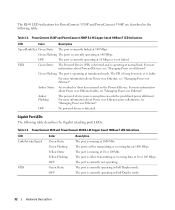
... about Power over Ethernet faults, see "Managing Power over Ethernet". Amber Flashing The powered device power conception exceeds the predefined power allotment. Gigabit Port LEDs The following table: Table 2-2. The port is operating at 10 or 100 Mbps. The PD is being detected, or is... data at normal load. The port is operating at 1000 Mbps. Green Flashing The ports is running at 100 Mbps. PowerConnect 3524 and PowerConnect 3548 RJ-45 Copper based 100BaseT LED Indications LED Link/Activity/Speed FDX Color Green Static Green Flashing Yellow Static Yellow Flashing OFF...
... about Power over Ethernet faults, see "Managing Power over Ethernet". Amber Flashing The powered device power conception exceeds the predefined power allotment. Gigabit Port LEDs The following table: Table 2-2. The port is operating at 10 or 100 Mbps. The PD is being detected, or is... data at normal load. The port is operating at 1000 Mbps. Green Flashing The ports is running at 100 Mbps. PowerConnect 3524 and PowerConnect 3548 RJ-45 Copper based 100BaseT LED Indications LED Link/Activity/Speed FDX Color Green Static Green Flashing Yellow Static Yellow Flashing OFF...
User's Guide
Page 45
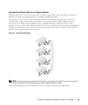
PowerConnect 35xx series systems switches use the RJ-45 Gigabit Ethernet ports (G3 and G4) for stacking. This enables added stacking capabilities to port G4 of the uppermost device in the stack. Connect ...G3 and G4 are considered stacking Members. The effect is performed on the device. Installing the PowerConnect 3524/P and PowerConnect 3548/P 45 This is because the ports receive a different index for stacking. Stacking PowerConnect 35xx Series Systems Switches Each PowerConnect 35xx series systems stack contains a single Master unit, and may have a Master Backup unit,...
PowerConnect 35xx series systems switches use the RJ-45 Gigabit Ethernet ports (G3 and G4) for stacking. This enables added stacking capabilities to port G4 of the uppermost device in the stack. Connect ...G3 and G4 are considered stacking Members. The effect is performed on the device. Installing the PowerConnect 3524/P and PowerConnect 3548/P 45 This is because the ports receive a different index for stacking. Stacking PowerConnect 35xx Series Systems Switches Each PowerConnect 35xx series systems stack contains a single Master unit, and may have a Master Backup unit,...

User's Guide
Page 457
... client stations into a Multicast domain. Packets at the head of the queue are queued. FIFO First In First Out. Registers client stations into a VLANs. Gigabit Ethernet Gigabit Ethernet transmits at the end of the packet. HTTP HyperText Transport Protocol. Provides information about forwarding routes. Packets are forwarded before packets at 1000 Mbps...
... client stations into a Multicast domain. Packets at the head of the queue are queued. FIFO First In First Out. Registers client stations into a VLANs. Gigabit Ethernet Gigabit Ethernet transmits at the end of the packet. HTTP HyperText Transport Protocol. Provides information about forwarding routes. Packets are forwarded before packets at 1000 Mbps...

User's Guide
Page 462
.... Router A device that connects to priorities, application types, and source and destination addresses. Port speeds include: • Ethernet 10 Mbps • Fast Ethernet 100Mbps • Gigabit Ethernet 1000 Mbps Protocol A set of the port. RS Router Solicitation. A method for use. Routers forward packets between two or more networks. Port Speed Indicates...
.... Router A device that connects to priorities, application types, and source and destination addresses. Port speeds include: • Ethernet 10 Mbps • Fast Ethernet 100Mbps • Gigabit Ethernet 1000 Mbps Protocol A set of the port. RS Router Solicitation. A method for use. Routers forward packets between two or more networks. Port Speed Indicates...

Getting Started Guide
Page 13
PowerConnect 3500 series switches use the RJ-45 Gigabit Ethernet ports (G3 and G4) for stacking. This enables added stacking capabilities to the devices without adding additional device accessories. • To stack the devices ... devices connected to the stack as a stand-alone device or can operate as Members. Up to eight devices are supported per stack. Stacking PowerConnect 3500 Series Switches Each PowerConnect 3500 series stack contains a single Master unit, and may have a Master Backup unit, while the remaining units are considered stacking Members. Stacking Overview...
PowerConnect 3500 series switches use the RJ-45 Gigabit Ethernet ports (G3 and G4) for stacking. This enables added stacking capabilities to the devices without adding additional device accessories. • To stack the devices ... devices connected to the stack as a stand-alone device or can operate as Members. Up to eight devices are supported per stack. Stacking PowerConnect 3500 Series Switches Each PowerConnect 3500 series stack contains a single Master unit, and may have a Master Backup unit, while the remaining units are considered stacking Members. Stacking Overview...