
User's Guide
Page 4
... 27 Port Description 27 PowerConnect 3524 Port Description 27 The back panel contains an RPS connector, console port, and power connector 28 PowerConnect 3548 Port Description 28 SFP Ports 29 RS-232 Console Port 29 Physical Dimensions 30 LED Definitions 30 Gigabit Port LEDs 32 System ...LEDs 33 Power Supplies 35 Stack ID Button 36 Reset Button 37 Ventilation System 37 3 Installing the PowerConnect 3524/P and PowerConnect 3548/P 39 Site Preparation 39 Unpacking 39 Package Contents 39...
... 27 Port Description 27 PowerConnect 3524 Port Description 27 The back panel contains an RPS connector, console port, and power connector 28 PowerConnect 3548 Port Description 28 SFP Ports 29 RS-232 Console Port 29 Physical Dimensions 30 LED Definitions 30 Gigabit Port LEDs 32 System ...LEDs 33 Power Supplies 35 Stack ID Button 36 Reset Button 37 Ventilation System 37 3 Installing the PowerConnect 3524/P and PowerConnect 3548/P 39 Site Preparation 39 Unpacking 39 Package Contents 39...
User's Guide
Page 27
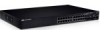
... in a stand-alone device. G4 which are copper ports. Ports G3 - RJ-45 ports designated as 1000Base-X SFP ports • 2 Gigabit ports - PowerConnect 3524 Front Panel 10/100 Base-T Ports 1, 3, 5, 7, ...23 System LEDs Reset Button Stacking Button Stacking LEDs 10/100 Base-T Ports 2, .... G2 which are fiber ports and ports G3- Hardware Description Port Description PowerConnect 3524 Port Description The Dell™ PowerConnect™ 3524 device is marked with the following figure illustrates the PowerConnect 3524 front panel. RS-232 based port The following ports: • 24 ...
... in a stand-alone device. G4 which are copper ports. Ports G3 - RJ-45 ports designated as 1000Base-X SFP ports • 2 Gigabit ports - PowerConnect 3524 Front Panel 10/100 Base-T Ports 1, 3, 5, 7, ...23 System LEDs Reset Button Stacking Button Stacking LEDs 10/100 Base-T Ports 2, .... G2 which are fiber ports and ports G3- Hardware Description Port Description PowerConnect 3524 Port Description The Dell™ PowerConnect™ 3524 device is marked with the following figure illustrates the PowerConnect 3524 front panel. RS-232 based port The following ports: • 24 ...
User's Guide
Page 28
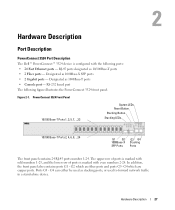
... • 2 Fiber ports - On the front panel are two buttons on the front panel. Designated as 1000Base-X SFP ports • 2 Gigabit ports - Figure 2-3. PowerConnect 3548 Front Panel 10/100 Base-T Ports 1, 3, 5, 7, ...47 System LEDs Reset Button Stacking Button Stacking LEDs 10/100 Base-T Ports 2,... LEDs. The Stack ID button is configured with the following figure illustrates the PowerConnect 3548 front panel. The second button is the Reset Button which is prevented. PowerConnect 3524 Back Panel Console Port RPS Connector Power Connector The back panel contains an RPS...
... • 2 Fiber ports - On the front panel are two buttons on the front panel. Designated as 1000Base-X SFP ports • 2 Gigabit ports - Figure 2-3. PowerConnect 3548 Front Panel 10/100 Base-T Ports 1, 3, 5, 7, ...47 System LEDs Reset Button Stacking Button Stacking LEDs 10/100 Base-T Ports 2,... LEDs. The Stack ID button is configured with the following figure illustrates the PowerConnect 3548 front panel. The second button is the Reset Button which is prevented. PowerConnect 3524 Back Panel Console Port RPS Connector Power Connector The back panel contains an RPS...
User's Guide
Page 32
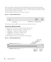
...linked at 1000 Mbps. The RJ-45 LED indications for PowerConnect 3524P and PowerConnect 3548P are described in Full Duplex mode. PowerConnect 3524P and PowerConnect 3548P RJ-45 Copper based 100BaseT LED Indications LED Color ...Gigabit Port LEDs The following table: Table 2-2. The port is faulty. The PD is being detected, or is currently operating in Half Duplex mode. 32 Hardware Description The port is running at transitional mode. For more information about Power over Ethernet faults, see "Managing Power over Ethernet". PowerConnect 3524 and PowerConnect...
...linked at 1000 Mbps. The RJ-45 LED indications for PowerConnect 3524P and PowerConnect 3548P are described in Full Duplex mode. PowerConnect 3524P and PowerConnect 3548P RJ-45 Copper based 100BaseT LED Indications LED Color ...Gigabit Port LEDs The following table: Table 2-2. The port is faulty. The PD is being detected, or is currently operating in Half Duplex mode. 32 Hardware Description The port is running at transitional mode. For more information about Power over Ethernet faults, see "Managing Power over Ethernet". PowerConnect 3524 and PowerConnect...
User's Guide
Page 45
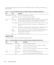
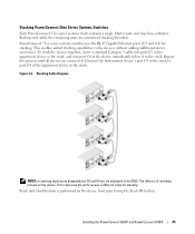
... Gigabit Ethernet ports (G3 and G4) for stacking. Stacking Cable Diagram NOTE: In stacking mode ports designated as G3 and G4 are connected. The effect is because the ports receive a different index for stacking. Installing the PowerConnect 3524/P and PowerConnect ...3548/P 45 Stack unit identification is performed on the device. Stacking PowerConnect 35xx Series Systems Switches Each PowerConnect 35xx series systems stack contains a single Master unit, and may ...
... Gigabit Ethernet ports (G3 and G4) for stacking. Stacking Cable Diagram NOTE: In stacking mode ports designated as G3 and G4 are connected. The effect is because the ports receive a different index for stacking. Installing the PowerConnect 3524/P and PowerConnect ...3548/P 45 Stack unit identification is performed on the device. Stacking PowerConnect 35xx Series Systems Switches Each PowerConnect 35xx series systems stack contains a single Master unit, and may ...


