User's Guide
Page 3
Contents 1 Introduction 11 System Description 11 PowerConnect 3524 11 PowerConnect 3524P 11 PowerConnect 3548 12 PowerConnect 3548P 12 Stacking Overview 12 Understanding the Stack Topology 13 Stacking Failover Topology 13 Stacking Members and Unit ID 13 Removing and Replacing Stacking Members 14 Exchanging Stacking Members 15 Switching from the Stack Master to the Backup Stack Master 17 Features Overview 17 IP Version 6 (IPv6) Support 17...
Contents 1 Introduction 11 System Description 11 PowerConnect 3524 11 PowerConnect 3524P 11 PowerConnect 3548 12 PowerConnect 3548P 12 Stacking Overview 12 Understanding the Stack Topology 13 Stacking Failover Topology 13 Stacking Members and Unit ID 13 Removing and Replacing Stacking Members 14 Exchanging Stacking Members 15 Switching from the Stack Master to the Backup Stack Master 17 Features Overview 17 IP Version 6 (IPv6) Support 17...

User's Guide
Page 4
... Console Port 29 Physical Dimensions 30 LED Definitions 30 Gigabit Port LEDs 32 System LEDs 33 Power Supplies 35 Stack ID Button 36 Reset Button 37 Ventilation System 37 3 Installing the PowerConnect 3524/P and PowerConnect 3548/P 39 Site Preparation 39 Unpacking 39 Package Contents 39 Unpacking the Device 40 Mounting the Device 40 Installing...
... Console Port 29 Physical Dimensions 30 LED Definitions 30 Gigabit Port LEDs 32 System LEDs 33 Power Supplies 35 Stack ID Button 36 Reset Button 37 Ventilation System 37 3 Installing the PowerConnect 3524/P and PowerConnect 3548/P 39 Site Preparation 39 Unpacking 39 Package Contents 39 Unpacking the Device 40 Mounting the Device 40 Installing...
User's Guide
Page 11
...PowerConnect 3524 is a stackable device, but also operates as stacking ports when the device is stacked. PowerConnect units can function either as stacking ports when the device is stacked. The PowerConnect 3524 and 3548 series include the following device types: • PowerConnect 3524 • PowerConnect 3524P • PowerConnect 3548 • PowerConnect 3548P PowerConnect 3524 The PowerConnect 3524... device also provides one RS-232 console port. Introduction Dell™ PowerConnect™ 3524/3548 and PowerConnect 3524P/3548P are stackable, advanced multi-layer devices.
...PowerConnect 3524 is a stackable device, but also operates as stacking ports when the device is stacked. PowerConnect units can function either as stacking ports when the device is stacked. The PowerConnect 3524 and 3548 series include the following device types: • PowerConnect 3524 • PowerConnect 3524P • PowerConnect 3548 • PowerConnect 3548P PowerConnect 3524 The PowerConnect 3524... device also provides one RS-232 console port. Introduction Dell™ PowerConnect™ 3524/3548 and PowerConnect 3524P/3548P are stackable, advanced multi-layer devices.

User's Guide
Page 12
...-based interface • SNMP Management Station • Command Line Interface (CLI) PowerConnect 3524/P and PowerConnect 3548/P devices support stacking up to forward traffic when the device is stacked. All other devices are selected as a stand-alone device. PowerConnect 3548 and PowerConnect 3548P Stacking Overview PowerConnect 3524/P and PowerConnect 3548/P stacking provides multiple switch management through which can be used to eight units...
...-based interface • SNMP Management Station • Command Line Interface (CLI) PowerConnect 3524/P and PowerConnect 3548/P devices support stacking up to forward traffic when the device is stacked. All other devices are selected as a stand-alone device. PowerConnect 3548 and PowerConnect 3548P Stacking Overview PowerConnect 3524/P and PowerConnect 3548/P stacking provides multiple switch management through which can be used to eight units...
User's Guide
Page 13
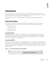
.... An SNMP message is automatically generated, but no stack management action is connected to Stacking Failover Topology. However, the stacking link or stacking member must be reconnected to the stacking configuration. Introduction 13 With the PowerConnect 3524/P and PowerConnect 3548/P stack, the system automatically switches to ensure the stacking integrity. In the Stacking Failover topology, devices operate in the ring becomes...
.... An SNMP message is automatically generated, but no stack management action is connected to Stacking Failover Topology. However, the stacking link or stacking member must be reconnected to the stacking configuration. Introduction 13 With the PowerConnect 3524/P and PowerConnect 3548/P stack, the system automatically switches to ensure the stacking integrity. In the Stacking Failover topology, devices operate in the ring becomes...
User's Guide
Page 15
... Unit ID, the previous device configuration is used to the inserted stack member. For example, • If a PowerConnect 3524/P replaces PowerConnect 3524/P, all port configurations remain the same. • If a PowerConnect 3548/P replaces the PowerConnect 3548/P, all units in the Master unit is applied to configure the stack. Only ports which are physically present are displayed in the...
... Unit ID, the previous device configuration is used to the inserted stack member. For example, • If a PowerConnect 3524/P replaces PowerConnect 3524/P, all port configurations remain the same. • If a PowerConnect 3548/P replaces the PowerConnect 3548/P, all units in the Master unit is applied to configure the stack. Only ports which are physically present are displayed in the...
User's Guide
Page 17
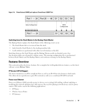
... the network infrastructure. PowerConnect 3548/P port replaces PowerConect 3524/P Port Same Configuration Same Configuration Switching from the Stack Master to the Backup Stack Master The Backup Master replaces the Stack Master if the following events occur: • The Stack Master fails or is removed from the stack. • Links from the Stack Master to the stacking members fails. •...
... the network infrastructure. PowerConnect 3548/P port replaces PowerConect 3524/P Port Same Configuration Same Configuration Switching from the Stack Master to the Backup Stack Master The Backup Master replaces the Stack Master if the following events occur: • The Stack Master fails or is removed from the stack. • Links from the Stack Master to the stacking members fails. •...
User's Guide
Page 27
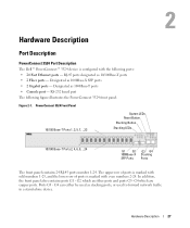
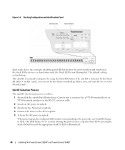
...; 24 Fast Ethernet ports - Figure 2-1. G4 can either be used as 1000Base-T ports • Console port - Designated as stacking ports, or used to forward network traffic in a stand-alone device. The upper row of ports is marked with odd numbers... - In addition, the front panel also contains ports G1 - Hardware Description Port Description PowerConnect 3524 Port Description The Dell™ PowerConnect™ 3524 device is marked with the following figure illustrates the PowerConnect 3524 front panel. G4 which are copper ports. RJ-45 ports designated as 1000Base-X SFP ports...
...; 24 Fast Ethernet ports - Figure 2-1. G4 can either be used as 1000Base-T ports • Console port - Designated as stacking ports, or used to forward network traffic in a stand-alone device. The upper row of ports is marked with odd numbers... - In addition, the front panel also contains ports G1 - Hardware Description Port Description PowerConnect 3524 Port Description The Dell™ PowerConnect™ 3524 device is marked with the following figure illustrates the PowerConnect 3524 front panel. G4 which are copper ports. RJ-45 ports designated as 1000Base-X SFP ports...
User's Guide
Page 28
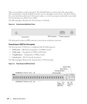
...Stack ID button is used to manually reset the device. The second button is the Reset Button which is used to select the unit number. The Reset button does not extend beyond the unit's front panel surface, so reset by pressing it accidentally is configured with the following figure illustrates the PowerConnect 3524... back: Figure 2-2. Figure 2-3. PowerConnect 3548 Port Description The PowerConnect 3548 device is prevented. PowerConnect 3524 Back Panel Console Port RPS Connector Power Connector ...
...Stack ID button is used to manually reset the device. The second button is the Reset Button which is used to select the unit number. The Reset button does not extend beyond the unit's front panel surface, so reset by pressing it accidentally is configured with the following figure illustrates the PowerConnect 3524... back: Figure 2-2. Figure 2-3. PowerConnect 3548 Port Description The PowerConnect 3548 device is prevented. PowerConnect 3524 Back Panel Console Port RPS Connector Power Connector ...
User's Guide
Page 32
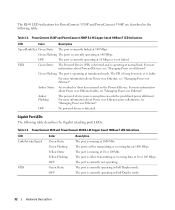
The RJ-45 LED indications for PowerConnect 3524P and PowerConnect 3548P are described in the following table describes the Gigabit (stacking port) LEDs: Table 2-3. OFF The port is running at 10 or 100Mbs. Amber Static An overload or short has occurred on the Powered Device. PowerConnect 3524 and PowerConnect 3548 RJ-45 Copper based 100BaseT LED Indications LED...
The RJ-45 LED indications for PowerConnect 3524P and PowerConnect 3548P are described in the following table describes the Gigabit (stacking port) LEDs: Table 2-3. OFF The port is running at 10 or 100Mbs. Amber Static An overload or short has occurred on the Powered Device. PowerConnect 3524 and PowerConnect 3548 RJ-45 Copper based 100BaseT LED Indications LED...

User's Guide
Page 35
... definition. The front panel "RPS" LED indicates whether the external EPS-470 is not designated as Stacking Unit N. The device is connected. The PowerConnect 3524/P and PowerConnect 3548/P devices have an internal power supply (12 Volt). The AC power supply unit uses a standard... connector. DC Power Supply Unit The PowerConnect 3524 and PowerConnect 3548 switches connect to an external RPS-600 unit to a PowerConnect RPS-600 unit. No configuration is connected. The Stacking LEDs are numbered 1- 8. The front panel "RPS" LED indicates whether...
... definition. The front panel "RPS" LED indicates whether the external EPS-470 is not designated as Stacking Unit N. The device is connected. The PowerConnect 3524/P and PowerConnect 3548/P devices have an internal power supply (12 Volt). The AC power supply unit uses a standard... connector. DC Power Supply Unit The PowerConnect 3524 and PowerConnect 3548 switches connect to an external RPS-600 unit to a PowerConnect RPS-600 unit. No configuration is connected. The Stacking LEDs are numbered 1- 8. The front panel "RPS" LED indicates whether...
User's Guide
Page 37
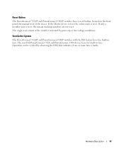
... reset. The single reset circuit of the device. Hardware Description 37 The non-PoE PowerConnect 3524 and PowerConnect 3548 devices have five built-in fans. Reset Button The PowerConnect 3524/P and PowerConnect 3548/P switches have a reset button, located on the front panel, for manual reset of the switch is reset, the remain stacking members are not reset.
... reset. The single reset circuit of the device. Hardware Description 37 The non-PoE PowerConnect 3524 and PowerConnect 3548 devices have five built-in fans. Reset Button The PowerConnect 3524/P and PowerConnect 3548/P switches have a reset button, located on the front panel, for manual reset of the switch is reset, the remain stacking members are not reset.
User's Guide
Page 44
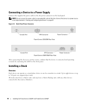
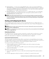
... connect the power cable to 384 ports are supported per stack. Up to eight devices or up to a grounded AC outlet at this time. Back-Panel Power Connector Console Port RPS Connector Power Connector PowerConnect 3524/3548 Rear View Console Port EPS Connector PowerConnect 3524P/3548P Rear View Power Connector After connecting the device to...
... connect the power cable to 384 ports are supported per stack. Up to eight devices or up to a grounded AC outlet at this time. Back-Panel Power Connector Console Port RPS Connector Power Connector PowerConnect 3524/3548 Rear View Console Port EPS Connector PowerConnect 3524P/3548P Rear View Power Connector After connecting the device to...
User's Guide
Page 45
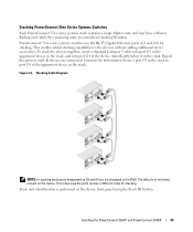
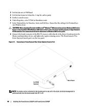
... systems switches use the RJ-45 Gigabit Ethernet ports (G3 and G4) for stacking. The effect is of the device immediately below it in the stack. Installing the PowerConnect 3524/P and PowerConnect 3548/P 45 Figure 3-5. Stacking PowerConnect 35xx Series Systems Switches Each PowerConnect 35xx series systems stack contains a single Master unit, and may have a Master Backup unit, while the...
... systems switches use the RJ-45 Gigabit Ethernet ports (G3 and G4) for stacking. The effect is of the device immediately below it in the stack. Installing the PowerConnect 3524/P and PowerConnect 3548/P 45 Figure 3-5. Stacking PowerConnect 35xx Series Systems Switches Each PowerConnect 35xx series systems stack contains a single Master unit, and may have a Master Backup unit, while the...
User's Guide
Page 46
The unit ID is illuminated. 46 Installing the PowerConnect 3524/P and PowerConnect 3548/P Figure 3-6. When powering up, the configured LED number (corresponding to the previously saved unit ID) begins to the AC receptacle. 5 Activate the AC power ... is stand-alone. Unit ID Selection Process The unit ID selection process is as follows: 1 Ensure that defines the unit's position and function in the stack. The default setting is not illuminated. The unit ID is connected to a VT100 terminal device or VT100 terminal emulator via the RS-232 crossover cable...
The unit ID is illuminated. 46 Installing the PowerConnect 3524/P and PowerConnect 3548/P Figure 3-6. When powering up, the configured LED number (corresponding to the previously saved unit ID) begins to the AC receptacle. 5 Activate the AC power ... is stand-alone. Unit ID Selection Process The unit ID selection process is as follows: 1 Ensure that defines the unit's position and function in the stack. The default setting is not illuminated. The unit ID is connected to a VT100 terminal device or VT100 terminal emulator via the RS-232 crossover cable...
User's Guide
Page 47
...called the Master unit in the device being configured as per the "Stacking Cable Diagram" on page 45 before powering up and their Stack IDs are master-enabled units. Installing the PowerConnect 3524/P and PowerConnect 3548/P 47 Performing the steps one unit at a time will allow... release notes from the Dell Support website at support.dell.com. Because the stack operates as a data terminal equipment (DTE) connector. Pressing the Stack ID button again advances the Stack ID to a console. However, the entire stack should be connected to select the Stack ID for sufficient time ...
...called the Master unit in the device being configured as per the "Stacking Cable Diagram" on page 45 before powering up and their Stack IDs are master-enabled units. Installing the PowerConnect 3524/P and PowerConnect 3548/P 47 Performing the steps one unit at a time will allow... release notes from the Dell Support website at support.dell.com. Because the stack operates as a data terminal equipment (DTE) connector. Pressing the Stack ID button again advances the Stack ID to a console. However, the entire stack should be connected to select the Stack ID for sufficient time ...
User's Guide
Page 48
... on the rear panel. With Windows 2000 Service Pack 2, the arrow keys function properly in the stack, but stack management is performed only from the stack master (unit ID 1 or 2). 48 Installing the PowerConnect 3524/P and PowerConnect 3548/P Connecting to PowerConnect 35xx Series Systems Console Port To VT100 Terminal Back Panel NOTE: A console can be connected to...
... on the rear panel. With Windows 2000 Service Pack 2, the arrow keys function properly in the stack, but stack management is performed only from the stack master (unit ID 1 or 2). 48 Installing the PowerConnect 3524/P and PowerConnect 3548/P Connecting to PowerConnect 35xx Series Systems Console Port To VT100 Terminal Back Panel NOTE: A console can be connected to...
User's Guide
Page 82
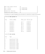
... information for a stacked devices using the CLI commands: console# show system id Unit ---1 2 3 4 5 6 7 8 Serial number 893658972 893658973 893658974 893658975 893658976 893658977 893658978 893658979 Asset tag --------mkt-1 mkt-2 mkt-3 mkt-4 mkt-5 mkt-6 mkt-7 mkt-8 Service tag ----------89788978 89788979 89788980 89788981 89788982 89788983 89788984 89788985 console# show system Unit ---1 2 3 4 5 6 7 8 Type PowerConnect 3524 PowerConnect 3524 PowerConnect 3524 PowerConnect 3524P PowerConnect 3524P PowerConnect 3524P PowerConnect 3524P PowerConnect 3524P 82 Configuring System...
... information for a stacked devices using the CLI commands: console# show system id Unit ---1 2 3 4 5 6 7 8 Serial number 893658972 893658973 893658974 893658975 893658976 893658977 893658978 893658979 Asset tag --------mkt-1 mkt-2 mkt-3 mkt-4 mkt-5 mkt-6 mkt-7 mkt-8 Service tag ----------89788978 89788979 89788980 89788981 89788982 89788983 89788984 89788985 console# show system Unit ---1 2 3 4 5 6 7 8 Type PowerConnect 3524 PowerConnect 3524 PowerConnect 3524 PowerConnect 3524P PowerConnect 3524P PowerConnect 3524P PowerConnect 3524P PowerConnect 3524P 82 Configuring System...


