User's Guide
Page 33
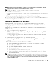
...illuminated (green or amber) indicating that you have the latest service packs installed. Dell PowerConnect 28xx Systems User Guide 33 To connect the device to the network: 1 Attach one end of a Twisted-Pair cable to the device's RJ-45 connector and the other end to each port ... (not Windows keys). d Set flow control to the device Console port, perform the following is for monitoring and configuring the device. To use the Console port, the following : 1 Connect the supplied RS-232 crossover cable to the console. This will damage the Ethernet device. To connect a terminal to...
...illuminated (green or amber) indicating that you have the latest service packs installed. Dell PowerConnect 28xx Systems User Guide 33 To connect the device to the network: 1 Attach one end of a Twisted-Pair cable to the device's RJ-45 connector and the other end to each port ... (not Windows keys). d Set flow control to the device Console port, perform the following is for monitoring and configuring the device. To use the Console port, the following : 1 Connect the supplied RS-232 crossover cable to the console. This will damage the Ethernet device. To connect a terminal to...
User's Guide
Page 34
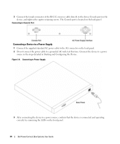
...captive retaining screws. Connecting to Console Port Connecting a Device to a Power Supply 1 Connect the supplied standard AC power cable to the AC connector on the back panel. 2 Do not connect the power cable to the device Console port on the front panel. 34 Dell PowerConnect 28xx Systems User Guide 3 ...Connect the female connector of the RS-232 crossover cable directly to a grounded AC...
...captive retaining screws. Connecting to Console Port Connecting a Device to a Power Supply 1 Connect the supplied standard AC power cable to the AC connector on the back panel. 2 Do not connect the power cable to the device Console port on the front panel. 34 Dell PowerConnect 28xx Systems User Guide 3 ...Connect the female connector of the RS-232 crossover cable directly to a grounded AC...
User's Guide
Page 40
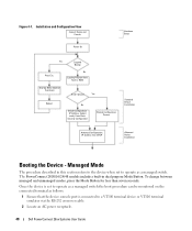
...Configuration Flow Connect Device and Console Power On Hardware Setup Press Esc Yes Suspend Bootup No Loading Program from flash to a VT100 terminal device or VT100 terminal emulator via the RS-232 crossover cable. 2 Locate an AC power receptacle. 40 Dell PowerConnect 28xx Systems User Guide Once... the device is set to operate as follows: 1 Ensure that the device console port is connected to RAM Startup Menu (Special Functions) ...
...Configuration Flow Connect Device and Console Power On Hardware Setup Press Esc Yes Suspend Bootup No Loading Program from flash to a VT100 terminal device or VT100 terminal emulator via the RS-232 crossover cable. 2 Locate an AC power receptacle. 40 Dell PowerConnect 28xx Systems User Guide Once... the device is set to operate as follows: 1 Ensure that the device console port is connected to RAM Startup Menu (Special Functions) ...

Getting Started Guide
Page 16
b Set the data rate to none. d Set flow control to 9600 baud. The PowerConnect 2808/16/24/48 models include a built-in HyperTerminal's VT100 emulation. The console port enables a connection to 8 data bits, 1 stop bit, and no parity. With Windows 2000 ...cable with Microsoft® Windows 2000, Windows XP, or Windows Vista, ensure that the device console port is required: • VT100 compatible terminal or a desktop or portable system with a serial port and running terminal emulation software for monitoring and configuring the device. The PowerConnect 2800 series Console...
b Set the data rate to none. d Set flow control to 9600 baud. The PowerConnect 2808/16/24/48 models include a built-in HyperTerminal's VT100 emulation. The console port enables a connection to 8 data bits, 1 stop bit, and no parity. With Windows 2000 ...cable with Microsoft® Windows 2000, Windows XP, or Windows Vista, ensure that the device console port is required: • VT100 compatible terminal or a desktop or portable system with a serial port and running terminal emulation software for monitoring and configuring the device. The PowerConnect 2800 series Console...
Getting Started Guide
Page 17
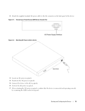
2 Attach the supplied standard AC power cable to PowerConnect 2800 Series Console Port Figure 3-2. Figure 3-1. Connecting to the AC connector on the front panel. Starting and Configuring the Device 15 Attaching AC Power cable to device 3 Locate an AC power receptacle. 4 Deactivate the AC power receptacle. 5 Connect the device to the AC receptacle. 6 Activate the AC power receptacle. 7 After activating the AC power receptacle, confirm that the device is connected and operating correctly by examining the LEDs on the back panel of the device.
2 Attach the supplied standard AC power cable to PowerConnect 2800 Series Console Port Figure 3-2. Figure 3-1. Connecting to the AC connector on the front panel. Starting and Configuring the Device 15 Attaching AC Power cable to device 3 Locate an AC power receptacle. 4 Deactivate the AC power receptacle. 5 Connect the device to the AC receptacle. 6 Activate the AC power receptacle. 7 After activating the AC power receptacle, confirm that the device is connected and operating correctly by examining the LEDs on the back panel of the device.


