
User's Guide
Page 3
... 16 2 Hardware Description 17 Switch Port Configurations 17 PowerConnect 28xx Front and Back Panel Port Description 17 Physical Dimensions 21 LED Definitions 21 Power LED 22 Managed Mode LED 22 Fan LED (2824/2848 only 22 Port LEDs 22 Managed Mode Button 23 Switch Ventilation Fan 23 Cables, Port Connections, and Pinout Information 24 1000BASE...
... 16 2 Hardware Description 17 Switch Port Configurations 17 PowerConnect 28xx Front and Back Panel Port Description 17 Physical Dimensions 21 LED Definitions 21 Power LED 22 Managed Mode LED 22 Fan LED (2824/2848 only 22 Port LEDs 22 Managed Mode Button 23 Switch Ventilation Fan 23 Cables, Port Connections, and Pinout Information 24 1000BASE...
User's Guide
Page 4
...DHCP Server 45 4 Contents Managed Mode 40 Initial Configuration - Power Connectors 26 Internal Power Supply Connector 26 3 Installing the PowerConnect Device 27 Installation Precautions 27 Site Requirements 28 Unpacking 28 Package Contents 28 Unpacking the Device 28 Mounting the Device 29 ...Connecting the Terminal to the Device 33 Connecting a Device to a Power Supply 34 Port Connections, Cables, and Pinout Information 35 RJ-45 Connections for 10/100/1000BaseT Ports 35 Port Default Settings 36 Auto-Negotiation 36 MDI/MDIX 36 Flow Control 36 Back Pressure 36 Switching...
...DHCP Server 45 4 Contents Managed Mode 40 Initial Configuration - Power Connectors 26 Internal Power Supply Connector 26 3 Installing the PowerConnect Device 27 Installation Precautions 27 Site Requirements 28 Unpacking 28 Package Contents 28 Unpacking the Device 28 Mounting the Device 29 ...Connecting the Terminal to the Device 33 Connecting a Device to a Power Supply 34 Port Connections, Cables, and Pinout Information 35 RJ-45 Connections for 10/100/1000BaseT Ports 35 Port Default Settings 36 Auto-Negotiation 36 MDI/MDIX 36 Flow Control 36 Back Pressure 36 Switching...

User's Guide
Page 9
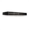
... The following figure illustrates the PowerConnect 2808 front panel. The switches are ideal for installing, configuring and maintaining the PowerConnect 2808, PowerConnect 2816, PowerConnect 2824, and PowerConnect 2848 Webmanaged Gigabit Ethernet switches. System Description This section describes the hardware configurations of the PowerConnect 28xx. Dell PowerConnect 28xx Systems User Guide 9 The PowerConnect 28xx switches can be used to connect workstations and other network devices...
... The following figure illustrates the PowerConnect 2808 front panel. The switches are ideal for installing, configuring and maintaining the PowerConnect 2808, PowerConnect 2816, PowerConnect 2824, and PowerConnect 2848 Webmanaged Gigabit Ethernet switches. System Description This section describes the hardware configurations of the PowerConnect 28xx. Dell PowerConnect 28xx Systems User Guide 9 The PowerConnect 28xx switches can be used to connect workstations and other network devices...
User's Guide
Page 12
...are detected: • Cable Type and Status • Cable Length • Fault-Distance 12 Dell PowerConnect 28xx Systems User Guide Flow Control Support (IEEE802.3X) On Full Duplex links (FDX), the ...segment, and to automatically configure both Ethernet switches to take maximum advantage of up to 10K bytes. Auto Negotiation Auto negotiation allows an Ethernet switch to advertise modes of this facility are ...Dependent Interface (MDI) and the standard wiring for hubs and switches is crossed or straight through. Virtual Cable Testing (VCT) VCT technology provides the mechanism to...
...are detected: • Cable Type and Status • Cable Length • Fault-Distance 12 Dell PowerConnect 28xx Systems User Guide Flow Control Support (IEEE802.3X) On Full Duplex links (FDX), the ...segment, and to automatically configure both Ethernet switches to take maximum advantage of up to 10K bytes. Auto Negotiation Auto negotiation allows an Ethernet switch to advertise modes of this facility are ...Dependent Interface (MDI) and the standard wiring for hubs and switches is crossed or straight through. Virtual Cable Testing (VCT) VCT technology provides the mechanism to...

User's Guide
Page 13
...frames. Dell PowerConnect 28xx Systems User Guide 13 When Multicast groups are associated with ports by reducing power usage of the layer 2 multicast domain even though there is an effort to -many connections for untagged frames. VLAN-aware MAC-based Switching in ...Unmanaged Mode In Unmanaged Mode, the switch performs classic bridging. MAC Address Supported Features MAC Address Capacity Support The PowerConnect 2808, 2816, 2824 switches support a total of 8K MAC addresses, and the PowerConnect 2848 supports...
...frames. Dell PowerConnect 28xx Systems User Guide 13 When Multicast groups are associated with ports by reducing power usage of the layer 2 multicast domain even though there is an effort to -many connections for untagged frames. VLAN-aware MAC-based Switching in ...Unmanaged Mode In Unmanaged Mode, the switch performs classic bridging. MAC Address Supported Features MAC Address Capacity Support The PowerConnect 2808, 2816, 2824 switches support a total of 8K MAC addresses, and the PowerConnect 2848 supports...
User's Guide
Page 14
... traffic by the switch. Packets are forwarded by the RADIUS server, the user is authenticated by the device from work stations configured for Multicast sessions, and which target port receives copies of incoming and outgoing packets from physical link disruption 14 Dell PowerConnect 28xx Systems User ... are collections of the six aggregated links may be grouped in the same VLAN. All nodes connected to these ports accept and attempt to six aggregated links. Each of switching ports that comprise a single broadcast domain. Users can be defined with up to process these ...
... traffic by the switch. Packets are forwarded by the RADIUS server, the user is authenticated by the device from work stations configured for Multicast sessions, and which target port receives copies of incoming and outgoing packets from physical link disruption 14 Dell PowerConnect 28xx Systems User ... are collections of the six aggregated links may be grouped in the same VLAN. All nodes connected to these ports accept and attempt to six aggregated links. Each of switching ports that comprise a single broadcast domain. Users can be defined with up to process these ...

User's Guide
Page 15
...decide whether its ports are actively forwarding traffic. During this delay, and can take 30-60 seconds for the switch Dell PowerConnect 28xx Systems User Guide 15 DHCP service is an extension to converge. Spanning Tree Protocol Features Spanning Tree Protocol... Dynamic Host Configuration Protocol is a standard Layer 2 switch requirement that allows bridges to enable faster convergence, without creating forwarding loops. • Higher bandwidth connections • Improved bandwidth granularity • High bandwidth server connectivity A LAG is composed of ports with a TFTP ...
...decide whether its ports are actively forwarding traffic. During this delay, and can take 30-60 seconds for the switch Dell PowerConnect 28xx Systems User Guide 15 DHCP service is an extension to converge. Spanning Tree Protocol Features Spanning Tree Protocol... Dynamic Host Configuration Protocol is a standard Layer 2 switch requirement that allows bridges to enable faster convergence, without creating forwarding loops. • Higher bandwidth connections • Improved bandwidth granularity • High bandwidth server connectivity A LAG is composed of ports with a TFTP ...

User's Guide
Page 17
... management modes and to right. On the left to reset the device. Hardware Description Switch Port Configurations PowerConnect 28xx Front and Back Panel Port Description The Dell™ PowerConnect™ 28xx switches use 10/100/1000BASE-T ports on or not. Figure 2-1. The Power LED on ... the front panel is powered on the front panel for connecting to indicate the port status. Dell PowerConnect 28xx Systems User Guide 17 PowerConnect 2808 Front Panel 2 On the front panel there are eight ports which indicates the Ethernet switch operational status and the management mode.
... management modes and to right. On the left to reset the device. Hardware Description Switch Port Configurations PowerConnect 28xx Front and Back Panel Port Description The Dell™ PowerConnect™ 28xx switches use 10/100/1000BASE-T ports on or not. Figure 2-1. The Power LED on ... the front panel is powered on the front panel for connecting to indicate the port status. Dell PowerConnect 28xx Systems User Guide 17 PowerConnect 2808 Front Panel 2 On the front panel there are eight ports which indicates the Ethernet switch operational status and the management mode.

User's Guide
Page 19
...the front panel indicates whether the device is powered on a combo port, and utilizes the information in all the control interfaces. Dell PowerConnect 28xx Systems User Guide 19 PowerConnect 2824 Front Panel On the front panel there are 24 ports which are LEDs to right. NOTE: Only one time. Port features...-45 port will be used . If both RJ-45 and SFP ports are determined by the physical connection used at any one of the two physical connections of a combo port can switch from the RJ-45 to reset the device. The system automatically detects the media used to transition between...
...the front panel indicates whether the device is powered on a combo port, and utilizes the information in all the control interfaces. Dell PowerConnect 28xx Systems User Guide 19 PowerConnect 2824 Front Panel On the front panel there are 24 ports which are LEDs to right. NOTE: Only one time. Port features...-45 port will be used . If both RJ-45 and SFP ports are determined by the physical connection used at any one of the two physical connections of a combo port can switch from the RJ-45 to reset the device. The system automatically detects the media used to transition between...

User's Guide
Page 20
... port status. A Mode push- 20 Dell PowerConnect 28xx Systems User Guide On each port, there are four SFP (Small Form-Factor Plugable) ports, designated as ports 45, 46, 47 and 48, for swappable optical transceiver, which offers high-speed 1000BASE-SX or 1000BASE-LX connection. NOTE: Only one of the two...by the physical connection used at any one time. Port features and port controls are numbered 1 to 48, top down and left to the SFP (or vice versa) without resetting the device. On the top right side of a combo port can switch from the RJ-45 to right. PowerConnect 2848 Front Panel ...
... port status. A Mode push- 20 Dell PowerConnect 28xx Systems User Guide On each port, there are four SFP (Small Form-Factor Plugable) ports, designated as ports 45, 46, 47 and 48, for swappable optical transceiver, which offers high-speed 1000BASE-SX or 1000BASE-LX connection. NOTE: Only one of the two...by the physical connection used at any one time. Port features and port controls are numbered 1 to 48, top down and left to the SFP (or vice versa) without resetting the device. On the top right side of a combo port can switch from the RJ-45 to right. PowerConnect 2848 Front Panel ...
User's Guide
Page 24
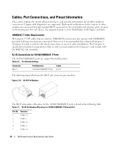
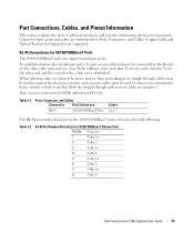
...number allocation for 10/100/ 1000BASE-T Ethernet Port Pin No 1 2 3 4 5 Function TxRx 1+ TxRx 1TxRx 2+ TxRx 2TxRx 3+ 24 Dell PowerConnect 28xx Systems User Guide RJ-45 Pin Number Allocation for the 10/100/1000BASE-T ports is used for 10/100/1000BASE-T Ports The 10/100... connector pin numbers. High-speed workstations, hubs, routers, or other switches are supported. RJ-45 Connections for 100BASE-TX connections also operate with the IEEE 802.3ab standards. Table 2-7. Copper cable diagnostics are connected through standard RJ-45 connectors to Half Duplex, Full Duplex, and ...
...number allocation for 10/100/ 1000BASE-T Ethernet Port Pin No 1 2 3 4 5 Function TxRx 1+ TxRx 1TxRx 2+ TxRx 2TxRx 3+ 24 Dell PowerConnect 28xx Systems User Guide RJ-45 Pin Number Allocation for the 10/100/1000BASE-T ports is used for 10/100/1000BASE-T Ports The 10/100... connector pin numbers. High-speed workstations, hubs, routers, or other switches are supported. RJ-45 Connections for 100BASE-TX connections also operate with the IEEE 802.3ab standards. Table 2-7. Copper cable diagnostics are connected through standard RJ-45 connectors to Half Duplex, Full Duplex, and ...

User's Guide
Page 25
... ground (common with transmitter ground) Receiver ground (common with transmitter ground) Receiver ground (common with transmitter ground) Dell PowerConnect 28xx Systems User Guide 25 laser output disabled on a combo port, and utilizes this information in the following table...connections of signal indication; SFP Pin Connections Pin No 1 2 3 4 5 6 7 8 9 10 11 12 13 14 Use Transmitter ground (common with receiver ground) Transmitter fault Transmitter disable; SFP Ports The PowerConnect 2824 switch supports two SFP transceivers combo ports, and the PowerConnect 2848 switch...
... ground (common with transmitter ground) Receiver ground (common with transmitter ground) Receiver ground (common with transmitter ground) Dell PowerConnect 28xx Systems User Guide 25 laser output disabled on a combo port, and utilizes this information in the following table...connections of signal indication; SFP Pin Connections Pin No 1 2 3 4 5 6 7 8 9 10 11 12 13 14 Use Transmitter ground (common with receiver ground) Transmitter fault Transmitter disable; SFP Ports The PowerConnect 2824 switch supports two SFP transceivers combo ports, and the PowerConnect 2848 switch...
User's Guide
Page 26
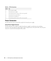
...Connections Pin No 15 16 17 18 19 20 Use Receiver power supply Transmitter power supply Transmitter ground (common with receiver ground) Transmitter non-inverted data in Transmitter inverted data in Transmitter ground (common with receiver ground) Power Connectors The PowerConnect 28xx is located on the back panel of the switch. 26 Dell PowerConnect... 28xx Systems User Guide Internal Power Supply Connector The PowerConnect 28xx supports a single internal power supply to provide power for switching ...
...Connections Pin No 15 16 17 18 19 20 Use Receiver power supply Transmitter power supply Transmitter ground (common with receiver ground) Transmitter non-inverted data in Transmitter inverted data in Transmitter ground (common with receiver ground) Power Connectors The PowerConnect 28xx is located on the back panel of the switch. 26 Dell PowerConnect... 28xx Systems User Guide Internal Power Supply Connector The PowerConnect 28xx supports a single internal power supply to provide power for switching ...

User's Guide
Page 27
..., and back of all switches installed on the same circuit as explained in the system documentation. Compare this section: • Ensure that the rack or cabinet housing the device is adequately secured to radiators and/or heat sources. • Ensure that the device is not restricted. 3 Dell PowerConnect 28xx Systems User Guide 27...
..., and back of all switches installed on the same circuit as explained in the system documentation. Compare this section: • Ensure that the rack or cabinet housing the device is adequately secured to radiators and/or heat sources. • Ensure that the device is not restricted. 3 Dell PowerConnect 28xx Systems User Guide 27...

User's Guide
Page 29
Install the device in a rack as the safety information for damage. Dell PowerConnect 28xx Systems User Guide 29 CAUTION Disconnect all cables from the bottom up to the mounting holes on the rack mounting bracket. CAUTION When mounting ... mounting options: • Installing in a Rack • Installing on a Flat Surface • Installing on the device line up . 5 Inspect the product for other devices that connect to or support the switch. Report any damage immediately.
Install the device in a rack as the safety information for damage. Dell PowerConnect 28xx Systems User Guide 29 CAUTION Disconnect all cables from the bottom up to the mounting holes on the rack mounting bracket. CAUTION When mounting ... mounting options: • Installing in a Rack • Installing on a Flat Surface • Installing on the device line up . 5 Inspect the product for other devices that connect to or support the switch. Report any damage immediately.
User's Guide
Page 32
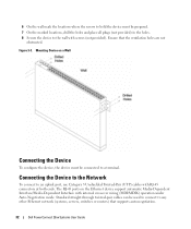
...Standard straight-through twisted-pair cables can be used to connect to any other Ethernet network (systems, servers, switches or routers) that the ventilation holes are not obstructed. Figure 3-3. Connecting the Device to the Network To connect to an uplink port, use Category 5 Unshielded Twisted-Pair...Connecting the Device To configure the device, the device must be prepared. 7 On the marked locations, drill the holes and place all plugs (not provided) in the holes. 8 Secure the device to the wall with screws (not provided). Ensure that supports auto-negotiation. 32 Dell PowerConnect...
...Standard straight-through twisted-pair cables can be used to connect to any other Ethernet network (systems, servers, switches or routers) that the ventilation holes are not obstructed. Figure 3-3. Connecting the Device to the Network To connect to an uplink port, use Category 5 Unshielded Twisted-Pair...Connecting the Device To configure the device, the device must be prepared. 7 On the marked locations, drill the holes and place all plugs (not provided) in the holes. 8 Secure the device to the wall with screws (not provided). Ensure that supports auto-negotiation. 32 Dell PowerConnect...
User's Guide
Page 33
... device. Use only twisted-pair cables with a female DB-9 connector for the Console port and the appropriate connector for Emulation mode. Dell PowerConnect 28xx Systems User Guide 33 As each twisted pair cable does not exceed 328 feet (100 meters) in models 28016/24/48. ...the other end to the device Console port, perform the following is for monitoring and configuring the device. To connect a terminal to a switch or server. 2 Make sure each connection is made, the link LED corresponding to FCC standards. With Windows 2000 Service Pack 2, the arrow keys function...
... device. Use only twisted-pair cables with a female DB-9 connector for the Console port and the appropriate connector for Emulation mode. Dell PowerConnect 28xx Systems User Guide 33 As each twisted pair cable does not exceed 328 feet (100 meters) in models 28016/24/48. ...the other end to the device Console port, perform the following is for monitoring and configuring the device. To connect a terminal to a switch or server. 2 Make sure each connection is made, the link LED corresponding to FCC standards. With Windows 2000 Service Pack 2, the arrow keys function...
User's Guide
Page 35
...for the 10/100/1000BaseT ports is lit. RJ-45 Connections for the twisted-pair ports, Tx pair on one transmission device (switch or hub) to Tx on one end is not established. When selecting cables to connect the device ports to their networking peers, straight through ...and crossover cables are copper twisted-pair ports. If the cabling is done such that Tx on the other cable end, and vice versa. Copper Cable and Optical Transceiver Diagnostics are summarized in the table following. Dell PowerConnect...
...for the 10/100/1000BaseT ports is lit. RJ-45 Connections for the twisted-pair ports, Tx pair on one transmission device (switch or hub) to Tx on one end is not established. When selecting cables to connect the device ports to their networking peers, straight through ...and crossover cables are copper twisted-pair ports. If the cabling is done such that Tx on the other cable end, and vice versa. Copper Cable and Optical Transceiver Diagnostics are summarized in the table following. Dell PowerConnect...
User's Guide
Page 36
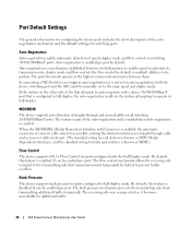
... mechanism established between a straight through and crossed cables on all switching 10/100/1000BaseT ports. If the station on switching 10/100/1000BaseT ports. When the MDI/MDIX (Media Dependent Interface...to its partner. Back Pressure The device supports back pressure for additional traffic. 36 Dell PowerConnect 28xx Systems User Guide By default, this feature is enabled per port. Auto-Negotiation...flow control (the flow control by default. Auto-negotiation is enabled. If connecting a NIC that transmission must be enabled per port. By default, this feature is enabled....
... mechanism established between a straight through and crossed cables on all switching 10/100/1000BaseT ports. If the station on switching 10/100/1000BaseT ports. When the MDI/MDIX (Media Dependent Interface...to its partner. Back Pressure The device supports back pressure for additional traffic. 36 Dell PowerConnect 28xx Systems User Guide By default, this feature is enabled per port. Auto-Negotiation...flow control (the flow control by default. Auto-negotiation is enabled. If connecting a NIC that transmission must be enabled per port. By default, this feature is enabled....
User's Guide
Page 39
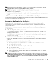
... completing all external connections, connect a terminal to the device to be used as an unmanaged switch, there is no need for a terminal connection. • A terminal connection is required if the device is to configure the device and for this product. NOTE: The PowerConnect 2808 has an internal... that you obtain the most recent revision of the user documentation from http://support.dell.com. NOTE: It is performed. 4 Dell PowerConnect 28xx Systems User Guide 39 After completing all external connections, procede as follows: • If the device is to be downloaded from ...
... completing all external connections, connect a terminal to the device to be used as an unmanaged switch, there is no need for a terminal connection. • A terminal connection is required if the device is to configure the device and for this product. NOTE: The PowerConnect 2808 has an internal... that you obtain the most recent revision of the user documentation from http://support.dell.com. NOTE: It is performed. 4 Dell PowerConnect 28xx Systems User Guide 39 After completing all external connections, procede as follows: • If the device is to be downloaded from ...


