
User's Guide
Page 3
Contents 1 Introduction 9 System Description 9 PowerConnect 2808 9 PowerConnect 2816 9 PowerConnect 2824 10 PowerConnect 2848 10 Summary of PowerConnect Models 11 Features 11 General Features 11 MAC Address Supported Features 13 Layer 2 Features 13 VLAN Supported Features 14 Spanning Tree Protocol Features 15 Class of Service (CoS) Features 16 Ethernet Switch Management Features 16 2 Hardware Description 17 Switch Port Configurations 17...
Contents 1 Introduction 9 System Description 9 PowerConnect 2808 9 PowerConnect 2816 9 PowerConnect 2824 10 PowerConnect 2848 10 Summary of PowerConnect Models 11 Features 11 General Features 11 MAC Address Supported Features 13 Layer 2 Features 13 VLAN Supported Features 14 Spanning Tree Protocol Features 15 Class of Service (CoS) Features 16 Ethernet Switch Management Features 16 2 Hardware Description 17 Switch Port Configurations 17...
User's Guide
Page 7
Configuring Rapid Spanning Tree 124 Configuring VLANs 126 Defining VLAN Members 126 VLAN Port Membership Table 128 Defining VLAN Ports Settings 130 Defining VLAN LAG Settings 131 Aggregating Ports 133 Defining LAG Membership 134 Multicast Forwarding Support 134 Defining Multicast Global Parameters 135 Adding ...Defining QoS Interface Settings 150 Defining Queue Settings 151 Mapping CoS Values to Queues 153 Mapping DSCP Values to Queues 154 A Managing the Device Using the CLI 157 Accessing the Device Through the CLI 157 Console Connection 157 Telnet Connection 157 Contents 7
Configuring Rapid Spanning Tree 124 Configuring VLANs 126 Defining VLAN Members 126 VLAN Port Membership Table 128 Defining VLAN Ports Settings 130 Defining VLAN LAG Settings 131 Aggregating Ports 133 Defining LAG Membership 134 Multicast Forwarding Support 134 Defining Multicast Global Parameters 135 Adding ...Defining QoS Interface Settings 150 Defining Queue Settings 151 Mapping CoS Values to Queues 153 Mapping DSCP Values to Queues 154 A Managing the Device Using the CLI 157 Accessing the Device Through the CLI 157 Console Connection 157 Telnet Connection 157 Contents 7

User's Guide
Page 13
... in Managed and Secure Modes In Managed or Secure mode, the switch system always performs VLAN-aware bridging. Layer 2 Features Green Ethernet Green Ethernet, also known as define the behavior of the frame are forwarded based on their destination MAC address). MAC Address Supported Features MAC Address Capacity Support The PowerConnect 2808, 2816, 2824 switches...
... in Managed and Secure Modes In Managed or Secure mode, the switch system always performs VLAN-aware bridging. Layer 2 Features Green Ethernet Green Ethernet, also known as define the behavior of the frame are forwarded based on their destination MAC address). MAC Address Supported Features MAC Address Capacity Support The PowerConnect 2808, 2816, 2824 switches...

User's Guide
Page 15
...same speed set to converge. Switches exchange configuration messages using specifically formatted frames and selectively enable and disable forwarding on the default VLAN, until a BootP server replies. The Fast Link option bypasses this time, STP detects possible loops, allowing time for status ...a valid runtime image. Rapid Spanning Tree (RSTP) detects uses of managing network parameter assignment from a network server upon system startup. The switch can take 30-60 seconds for the switch Dell PowerConnect 28xx Systems User Guide 15 The BootP client is operational if there is...
...same speed set to converge. Switches exchange configuration messages using specifically formatted frames and selectively enable and disable forwarding on the default VLAN, until a BootP server replies. The Fast Link option bypasses this time, STP detects possible loops, allowing time for status ...a valid runtime image. Rapid Spanning Tree (RSTP) detects uses of managing network parameter assignment from a network server upon system startup. The switch can take 30-60 seconds for the switch Dell PowerConnect 28xx Systems User Guide 15 The BootP client is operational if there is...

User's Guide
Page 16
...provides network traffic statistics. The PowerConnect 28xx system can be managed from any Web browser. The system provides a means to collect the statistics defined in the system. 16 Dell PowerConnect 28xx Systems User Guide The ...switches support one of service. The switches support four queues per port. Remote Monitoring Remote Monitoring (RMON) is classified and sent to the same Class of the 802.1Q (VLANs) standard. A CoS is a spin-off of Service. Ethernet Switch Management Features Web-Based Management...
...provides network traffic statistics. The PowerConnect 28xx system can be managed from any Web browser. The system provides a means to collect the statistics defined in the system. 16 Dell PowerConnect 28xx Systems User Guide The ...switches support one of service. The switches support four queues per port. Remote Monitoring Remote Monitoring (RMON) is classified and sent to the same Class of the 802.1Q (VLANs) standard. A CoS is a spin-off of Service. Ethernet Switch Management Features Web-Based Management...
User's Guide
Page 41
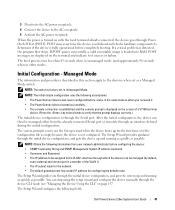
... Set-up wizard when the device boots up for configuring the default route. Dell PowerConnect 28xx Systems User Guide 41 3 Deactivate the AC power receptacle. 4 Connect ... when in unmanaged mode (and approximately 90 seconds when in this section apply to the VLAN 1 interface through an interface defined during the initial configuration. Initial Configuration - The Setup ... initial device configuration, and gets the device up and running as quickly as a Managed Mode switch. Managed Mode The information and procedures described in other modes. The Setup Wizard provides guidance ...
... Set-up wizard when the device boots up for configuring the default route. Dell PowerConnect 28xx Systems User Guide 41 3 Deactivate the AC power receptacle. 4 Connect ... when in unmanaged mode (and approximately 90 seconds when in this section apply to the VLAN 1 interface through an interface defined during the initial configuration. Initial Configuration - The Setup ... initial device configuration, and gets the device up and running as quickly as a Managed Mode switch. Managed Mode The information and procedures described in other modes. The Setup Wizard provides guidance ...
User's Guide
Page 43
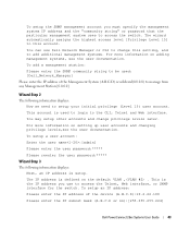
The wizard automatically assigns the highest access level [Privilege Level 15] to add additional management systems. For more information on the default VLAN ,(VLAN #2) . You can use to access the switch. This account is defined on setting up user accounts and changing... the IP subnet mask (A.B.C.D or nn):[255.255.255.224] Dell PowerConnect 28xx Systems User Guide 43 To setup an IP address: Please enter the IP address of the Management System (A.B.C.D) or wildcard(0.0.0.0) to manage from any Management Station:[0.0.0.0] Wizard Step 2 The following information displays: Next, an ...
The wizard automatically assigns the highest access level [Privilege Level 15] to add additional management systems. For more information on the default VLAN ,(VLAN #2) . You can use to access the switch. This account is defined on setting up user accounts and changing... the IP subnet mask (A.B.C.D or nn):[255.255.255.224] Dell PowerConnect 28xx Systems User Guide 43 To setup an IP address: Please enter the IP address of the Management System (A.B.C.D) or wildcard(0.0.0.0) to manage from any Management Station:[0.0.0.0] Wizard Step 2 The following information displays: Next, an ...
User's Guide
Page 126
... and not defined by the network device. To open the VLAN Membership page, click Switch→ VLAN→ VLAN Membership in which they are broadcast and Multicast domains. Auto - VLANs allow network traffic to flow more efficiently within the VLAN, a Layer 3 router functioning router is used. VLANs managed through software reduces the amount of a Local Area Network...
... and not defined by the network device. To open the VLAN Membership page, click Switch→ VLAN→ VLAN Membership in which they are broadcast and Multicast domains. Auto - VLANs allow network traffic to flow more efficiently within the VLAN, a Layer 3 router functioning router is used. VLANs managed through software reduces the amount of a Local Area Network...
User's Guide
Page 130
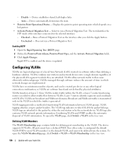
...port to which the specific port is updated. 130 Update with your book title VLAN Port Settings • Port - VLAN 4095 is configured on the port. - Enables or disables Ingress filtering on the port. The VLAN port settings are defined, and the device is not a member. Only tagged ... need to the device are 1-4094. To open the VLAN Port Settings page, click Switch→ VLAN→ Port Settings in the VLAN. • PVID (1-4095)- Defining VLAN Ports Settings The VLAN Port Settings page contains fields for managing ports that are accepted on the page 4 Click Apply ...
...port to which the specific port is updated. 130 Update with your book title VLAN Port Settings • Port - VLAN 4095 is configured on the port. - Enables or disables Ingress filtering on the port. The VLAN port settings are defined, and the device is not a member. Only tagged ... need to the device are 1-4094. To open the VLAN Port Settings page, click Switch→ VLAN→ Port Settings in the VLAN. • PVID (1-4095)- Defining VLAN Ports Settings The VLAN Port Settings page contains fields for managing ports that are accepted on the page 4 Click Apply ...

User's Guide
Page 131
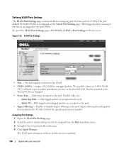
VLANs can either be composed of individual ports or of a VLAN. Figure 7-23. The VLAN Port Table opens. VLAN Port Table Defining VLAN LAG Settings The VLAN LAG Setting page provides parameters for managing LAGs that are tagged with your book title 131 Update with the LAGs ID specified by the PVID. Untagged packets entering the device are part of LAGs. To open the VLAN LAG Setting page, click Switch→ VLAN→ LAG Settings in the tree view. Displaying the VLAN Port Table 1 Open the VLAN Port Settings page. 2 Click Show All.
VLANs can either be composed of individual ports or of a VLAN. Figure 7-23. The VLAN Port Table opens. VLAN Port Table Defining VLAN LAG Settings The VLAN LAG Setting page provides parameters for managing LAGs that are tagged with your book title 131 Update with the LAGs ID specified by the PVID. Untagged packets entering the device are part of LAGs. To open the VLAN LAG Setting page, click Switch→ VLAN→ LAG Settings in the tree view. Displaying the VLAN Port Table 1 Open the VLAN Port Settings page. 2 Click Show All.
User's Guide
Page 137
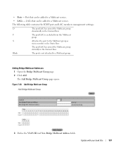
...added to a Multicast service. Blank The port is excluded from this Multicast group. The following table contains the IGMP port and LAG members management settings: D The port/LAG has joined the Multicast group dynamically in the Current Row. Update with your book title 137 • Ports... - Add Bridge Multicast Group 3 Define the VLAN ID and New Bridge Multicast Address fields. The port/LAG has joined the Multicast group statically in the Current Row. Port that can...
...added to a Multicast service. Blank The port is excluded from this Multicast group. The following table contains the IGMP port and LAG members management settings: D The port/LAG has joined the Multicast group dynamically in the Current Row. Update with your book title 137 • Ports... - Add Bridge Multicast Group 3 Define the VLAN ID and New Bridge Multicast Address fields. The port/LAG has joined the Multicast group statically in the Current Row. Port that can...
User's Guide
Page 139
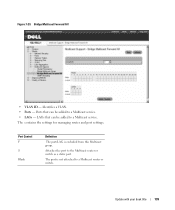
The contains the settings for managing router and port settings. Attaches the port to a Multicast service. • LAGs - Port Control F S Blank Definition The port/LAG is not attached to a Multicast service. Update with your book title 139 Ports that can be added to a Multicast router or switch. LAGs that can be added to the Multicast router or switch as a static port. The port is excluded from this Multicast group. Bridge Multicast Forward All • VLAN ID - Figure 7-29. Identifies a VLAN. • Ports -
The contains the settings for managing router and port settings. Attaches the port to a Multicast service. • LAGs - Port Control F S Blank Definition The port/LAG is not attached to a Multicast service. Update with your book title 139 Ports that can be added to a Multicast router or switch. LAGs that can be added to the Multicast router or switch as a static port. The port is excluded from this Multicast group. Bridge Multicast Forward All • VLAN ID - Figure 7-29. Identifies a VLAN. • Ports -
User's Guide
Page 147
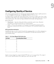
... traffic such as the egress VPT. 9 Update with high demand. All packets matching the user-defined specifications are based on a per port basis. Defines traffic management where packets being forwarded are classified together. • Action - CoS to Queue Mapping Table Default values CoS Value 0 1 2 3 4 5 6 7 Forwarding... can be assigned a high priority queue, while other traffic can be assigned a lower priority queue. VPT Tag Classification Information VLAN Priority Tags are user-definable. The assigned VPT is set on packet information, and packet field values such as...
... traffic such as the egress VPT. 9 Update with high demand. All packets matching the user-defined specifications are based on a per port basis. Defines traffic management where packets being forwarded are classified together. • Action - CoS to Queue Mapping Table Default values CoS Value 0 1 2 3 4 5 6 7 Forwarding... can be assigned a high priority queue, while other traffic can be assigned a lower priority queue. VPT Tag Classification Information VLAN Priority Tags are user-definable. The assigned VPT is set on packet information, and packet field values such as...

User's Guide
Page 149
... to best effort. Interface Trust settings override the global Trust mode setting. Enables or disables managing network traffic using Quality of Service (CoS) global parameters are : - The output queue assignment is determined by the IEEE802.1p VLAN priority tag (VPT) or by the DSCP field. The output queue assignment is enabled on...
... to best effort. Interface Trust settings override the global Trust mode setting. Enables or disables managing network traffic using Quality of Service (CoS) global parameters are : - The output queue assignment is determined by the IEEE802.1p VLAN priority tag (VPT) or by the DSCP field. The output queue assignment is enabled on...

User's Guide
Page 175
...telephone. Only one party can transmit information at a time. Supports data transfer rates of users which network traffic is supported. Provides device management via a standard web browser. E Egress Ports Ports from which retains the same system access rights. End System An end user device ...on the RADIUS server. Duplex Mode Permits simultaneous transmissions and reception of line commands used in addition to the VLAN configured on a network. Communities Specifies a group of Mpbs, where 10, 100 or 1000 Mbps is transmitted. Two parties can...
...telephone. Only one party can transmit information at a time. Supports data transfer rates of users which network traffic is supported. Provides device management via a standard web browser. E Egress Ports Ports from which retains the same system access rights. End System An end user device ...on the RADIUS server. Duplex Mode Permits simultaneous transmissions and reception of line commands used in addition to the VLAN configured on a network. Communities Specifies a group of Mpbs, where 10, 100 or 1000 Mbps is transmitted. Two parties can...

User's Guide
Page 185
Spanning Tree Protocol, 116, 124 Startup file, 80 Storm control, 110 STP, 15, 117, 125 System, 59 T TFTP, 181 Time Domain Reflectometry, 65 Tree view, 53 Trivial File Transfer Protocol, 181 Trunk Configuration Page, 106 Trust, 150 VLAN membership, 126 VLAN Port Membership Table, 128 VLAN priority, 147 VLANs, 126 W Web management system icons, 55 Weighted Round Robin, 151 Width, 21 U UDP, 181 Understanding the interface, 53 Uploading files, 82 User Data Protocol, 181 V Virtual Local Area Networks, 181 VLAN, 126, 130, 138, 181 VLAN ID, 115 Index 185
Spanning Tree Protocol, 116, 124 Startup file, 80 Storm control, 110 STP, 15, 117, 125 System, 59 T TFTP, 181 Time Domain Reflectometry, 65 Tree view, 53 Trivial File Transfer Protocol, 181 Trunk Configuration Page, 106 Trust, 150 VLAN membership, 126 VLAN Port Membership Table, 128 VLAN priority, 147 VLANs, 126 W Web management system icons, 55 Weighted Round Robin, 151 Width, 21 U UDP, 181 Understanding the interface, 53 Uploading files, 82 User Data Protocol, 181 V Virtual Local Area Networks, 181 VLAN, 126, 130, 138, 181 VLAN ID, 115 Index 185
Getting Started Guide
Page 18
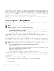
...a critical problem is not configured. NOTE: The initial simple configuration uses the following assumptions: • The PowerConnect device was never configured before, and is in Managed Mode, or if the configuration file is empty because the device is detected, the program flow stops. The...device configuration, and gets the device up and running as quickly as possible. Managed Mode The information and procedures described in other modes. The Setup Wizard guides you to the VLAN 1 interface through an interface defined during the initial configuration. When the power is...
...a critical problem is not configured. NOTE: The initial simple configuration uses the following assumptions: • The PowerConnect device was never configured before, and is in Managed Mode, or if the configuration file is empty because the device is detected, the program flow stops. The...device configuration, and gets the device up and running as quickly as possible. Managed Mode The information and procedures described in other modes. The Setup Wizard guides you to the VLAN 1 interface through an interface defined during the initial configuration. When the power is...

Getting Started Guide
Page 20
...to setup your initial privilege (Level 15) user account. This is defined on the default VLAN,(VLAN #1). The IP address is the IP address you use Dell Network Manager or CLI to change privilege levels later. You can use to access the Telnet, Web ... interface. Please enter the IP address of the Management System (A.B.C.D) or wildcard (0.0.0.0) to manage from which this setting, and to add additional management systems. For more information on adding management systems, see the user documentation. To add a management station: Please enter the SNMP community string to...
...to setup your initial privilege (Level 15) user account. This is defined on the default VLAN,(VLAN #1). The IP address is the IP address you use Dell Network Manager or CLI to change privilege levels later. You can use to access the Telnet, Web ... interface. Please enter the IP address of the Management System (A.B.C.D) or wildcard (0.0.0.0) to manage from which this setting, and to add additional management systems. For more information on adding management systems, see the user documentation. To add a management station: Please enter the SNMP community string to...

Getting Started Guide
Page 101
IP IP VLAN #2) ,VLAN IP Telnet SNMP IP IP 10.6.22.100:(A.B.C.D A.B.C.D) IP 255.255.255.224]:(nn Finally, setup the ... has been collected: SNMP Interface = [email protected] User Account setup = admin Password = Management IP address255.255.255.224 10.6.22.100 Default Gateway is 10.6.22.97 114
IP IP VLAN #2) ,VLAN IP Telnet SNMP IP IP 10.6.22.100:(A.B.C.D A.B.C.D) IP 255.255.255.224]:(nn Finally, setup the ... has been collected: SNMP Interface = [email protected] User Account setup = admin Password = Management IP address255.255.255.224 10.6.22.100 Default Gateway is 10.6.22.97 114

Getting Started Guide
Page 208
...interface for the switch. For more information on the default VLAN,(VLAN #2). UGDell Network Manager 또는 CLI UG U Mangagement Station aG사용할 SNMP aG [Dell_Network_Manager]P Management System 의 IP 주소 (A.B.C.D) 또는 Management Station IP 주 소 (0.0.0.0 0.0.0.0] 마법&#... Please enter the IP subnet mask (A.B.C.D or nn):[255.255.255.224]GO 그 다음 SGIP UGIP VLAN,(VLAN #2 UG SG SNMP IP UGIP aG장치의 IP 주소 OA.B.C.D a10.6.22.100GIP OA.B.C.D &#...
...interface for the switch. For more information on the default VLAN,(VLAN #2). UGDell Network Manager 또는 CLI UG U Mangagement Station aG사용할 SNMP aG [Dell_Network_Manager]P Management System 의 IP 주소 (A.B.C.D) 또는 Management Station IP 주 소 (0.0.0.0 0.0.0.0] 마법&#... Please enter the IP subnet mask (A.B.C.D or nn):[255.255.255.224]GO 그 다음 SGIP UGIP VLAN,(VLAN #2 UG SG SNMP IP UGIP aG장치의 IP 주소 OA.B.C.D a10.6.22.100GIP OA.B.C.D &#...


