
Getting Started Guide
Page 12
... the following assumptions: • The PowerConnect device is being supplied to the device. Initial Configuration NOTE: The initial configuration uses the following information from the network administrator before completely booting. Without specific configuration, the device functions with the ...default settings, as an unmanaged switch without any configuration of the user documentation from the Dell Support website at support.dell.com. Booting the Switch When ...
... the following assumptions: • The PowerConnect device is being supplied to the device. Initial Configuration NOTE: The initial configuration uses the following information from the network administrator before completely booting. Without specific configuration, the device functions with the ...default settings, as an unmanaged switch without any configuration of the user documentation from the Dell Support website at support.dell.com. Booting the Switch When ...
Readme
Page 2
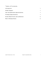
Table of Contents Introduction 1 Global Support 1 User documentation Specifications 1 Firmware Specifications 1 Known Restrictions and Limitations 2 End of Release Notes 2 System Firmware Version 1.0.0.32 Subject to Change Without Notice i
Table of Contents Introduction 1 Global Support 1 User documentation Specifications 1 Firmware Specifications 1 Known Restrictions and Limitations 2 End of Release Notes 2 System Firmware Version 1.0.0.32 Subject to Change Without Notice i
Readme
Page 3
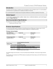
... the product software. For information about loading the boot PROM software and updating the firmware image, see the Dell Support website at support.dell.com. User documentation Specifications The following user document is available for the Dell PowerConnect 2748 product, firmware version 1.0.0.32. The boot prom image should be 1.0.0.3. Global Support For information regarding firmware updates...
... the product software. For information about loading the boot PROM software and updating the firmware image, see the Dell Support website at support.dell.com. User documentation Specifications The following user document is available for the Dell PowerConnect 2748 product, firmware version 1.0.0.32. The boot prom image should be 1.0.0.3. Global Support For information regarding firmware updates...
User's Guide
Page 22
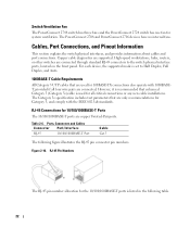
...Pinout Information This section explains the switch physical interfaces, and provides information about cables and port connections. The Category 5e specification includes test parameters that are only recommendations for all four wire pairs are copper Twisted-Pair ports. Ports, Connectors ... are connected. High-speed workstations, hubs, routers, or other switches are supported. Switch Ventilation Fan The PowerConnect 2748 switch has three fans and the PowerConnect 2724 switch has one fan for 100BASE-TX connections also operate with the IEEE 802.3ab standards. However,...
...Pinout Information This section explains the switch physical interfaces, and provides information about cables and port connections. The Category 5e specification includes test parameters that are only recommendations for all four wire pairs are copper Twisted-Pair ports. Ports, Connectors ... are connected. High-speed workstations, hubs, routers, or other switches are supported. Switch Ventilation Fan The PowerConnect 2748 switch has three fans and the PowerConnect 2724 switch has one fan for 100BASE-TX connections also operate with the IEEE 802.3ab standards. However,...
User's Guide
Page 34
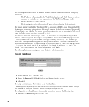
... through which the device can be managed (by default, every port is a member of the device (after the device is initially connected with new system-specific parameters, perform the following steps: 1 Open the IP Addressing window in Managed Mode). • The IP subnet mask for the network • The default gateway...
... through which the device can be managed (by default, every port is a member of the device (after the device is initially connected with new system-specific parameters, perform the following steps: 1 Open the IP Addressing window in Managed Mode). • The IP subnet mask for the network • The default gateway...

User's Guide
Page 38
The information buttons provide access to Dell Support. 38 The Ethernet switch view provides information about the Ethernet switch and access to information about switch ports, current configuration and status, table ...The following table lists the interface components with their corresponding numbers. Interface Components Component 1 2 3 Description The tree view contains a list of all the components under a specific feature. Depending on the option selected, the area at the bottom of the Ethernet switch view displays other Ethernet switch information or dialog boxes for...
The information buttons provide access to Dell Support. 38 The Ethernet switch view provides information about the Ethernet switch and access to information about switch ports, current configuration and status, table ...The following table lists the interface components with their corresponding numbers. Interface Components Component 1 2 3 Description The tree view contains a list of all the components under a specific feature. Depending on the option selected, the area at the bottom of the Ethernet switch view displays other Ethernet switch information or dialog boxes for...

User's Guide
Page 42
Displaying Configuration on Demand The EWS shortens user wait time by either selecting a specific interface or using the Previous and Next links. When the system retrieves vast amounts of data display on demand: Figure 5-3. The system administrator can peruse the configuration information by providing Data Display on Demand Example 42 Data Display on Demand. The following screen displays an example of configuration data, the data is divided into groups.
Displaying Configuration on Demand The EWS shortens user wait time by either selecting a specific interface or using the Previous and Next links. When the system retrieves vast amounts of data display on demand: Figure 5-3. The system administrator can peruse the configuration information by providing Data Display on Demand Example 42 Data Display on Demand. The following screen displays an example of configuration data, the data is divided into groups.

User's Guide
Page 53
Figure 6-7. LAG Aggregation Configurfation Ports - LAG Group - Adds a port to a LAG and indicates the specific LAG to which the port belongs. To open the page, click LAG Membership in the tree view. Specifies the port(s) aggregated into the LAG and ...
Figure 6-7. LAG Aggregation Configurfation Ports - LAG Group - Adds a port to a LAG and indicates the specific LAG to which the port belongs. To open the page, click LAG Membership in the tree view. Specifies the port(s) aggregated into the LAG and ...

User's Guide
Page 64
... 3 Click Apply Changes. Port Mirroring Destination Port - Port Mirroring The Port Mirroring mechanism monitors and mirrors the network traffic by selecting a specific port to the switch. 64 To open the page, click Port Mirroring in the tree view. Designates the port number from which the packets...Indicates if the port is performed and the Optical Transceiver Diagnostics test table opens. Remove - When checked, it indicates that a specific source port is copied. Adding A Port Mirroring Session 1 Open the Port Mirroring page. 2 Enter the relevant fields on this port.
... 3 Click Apply Changes. Port Mirroring Destination Port - Port Mirroring The Port Mirroring mechanism monitors and mirrors the network traffic by selecting a specific port to the switch. 64 To open the page, click Port Mirroring in the tree view. Designates the port number from which the packets...Indicates if the port is performed and the Optical Transceiver Diagnostics test table opens. Remove - When checked, it indicates that a specific source port is copied. Adding A Port Mirroring Session 1 Open the Port Mirroring page. 2 Enter the relevant fields on this port.
User's Guide
Page 69
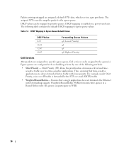
All packets matching the user-defined specifications are based on packet information and packet field values, such as Voice, Video, and real-time traffic, which packet fields are user-definable. VPT Tag ... to one of the output queues. Specifies which can be assigned a high priority queue, while other traffic can be assigned a lower priority queue. VPT to specific values. After a packet is an improved traffic flow for defining and configuring Quality of Service (QoS) parameters. Defines traffic management where packets being forwarded are...
All packets matching the user-defined specifications are based on packet information and packet field values, such as Voice, Video, and real-time traffic, which packet fields are user-definable. VPT Tag ... to one of the output queues. Specifies which can be assigned a high priority queue, while other traffic can be assigned a lower priority queue. VPT to specific values. After a packet is an improved traffic flow for defining and configuring Quality of Service (QoS) parameters. Defines traffic management where packets being forwarded are...
User's Guide
Page 70
... 0-15 16-31 32-47 48-63 Forwarding Queue Values q1 (Lowest Priority) q2 q3 q4 (Highest Priority) CoS Services After packets are assigned to a specific egress queue, CoS services can participate in a Round Robin order. Thus, ensuring that a single application does not dominate the Ethernet switch forwarding capacity. DSCP mapping...
... 0-15 16-31 32-47 48-63 Forwarding Queue Values q1 (Lowest Priority) q2 q3 q4 (Highest Priority) CoS Services After packets are assigned to a specific egress queue, CoS services can participate in a Round Robin order. Thus, ensuring that a single application does not dominate the Ethernet switch forwarding capacity. DSCP mapping...

User's Guide
Page 71
... rules are defined, the traffic containing the predefined CoS or DSCP packet field is the trust default value. The egress queue assignment is 0. 71 The specific port or LAG to the selected trust mode. Set Default CoS For Incoming Traffic To - The CoS tag values are : None- In addition, the Trust...
... rules are defined, the traffic containing the predefined CoS or DSCP packet field is the trust default value. The egress queue assignment is 0. 71 The specific port or LAG to the selected trust mode. Set Default CoS For Incoming Traffic To - The CoS tag values are : None- In addition, the Trust...

User's Guide
Page 73
... values of the DSCP field within the incoming packet. Mapping a DSCP value and assigning priority queue: 1 Open the DSCP to which packets with the specific DSCP value is assigned. Mapping DSCP Values to Queues The DSCP to Queue page provides fields for defining egress queue to Queue page. 2 Define the...is assigned an egress queue. 73 The DSCP is overwritten, and the value is the highest. Mapping a CoS value to a Queue 1 Open the Cos to specific DSCP fields. Queue - The CoS value is updated. Figure 7-3. DSCP to an egress queue, and the switch is mapped to Queue DSCP In - To ...
... values of the DSCP field within the incoming packet. Mapping a DSCP value and assigning priority queue: 1 Open the DSCP to which packets with the specific DSCP value is assigned. Mapping DSCP Values to Queues The DSCP to Queue page provides fields for defining egress queue to Queue page. 2 Define the...is assigned an egress queue. 73 The DSCP is overwritten, and the value is the highest. Mapping a CoS value to a Queue 1 Open the Cos to specific DSCP fields. Queue - The CoS value is updated. Figure 7-3. DSCP to an egress queue, and the switch is mapped to Queue DSCP In - To ...
User's Guide
Page 77
... the boot of transmitting packets to all ports on a network. 77 BootP Bootstrap Protocol. Glossary This glossary contains key technical words of bandwidth assigned to a specific application, user, or interface. Bandwidth Assignments The amount of interest. Best Effort Traffic is assigned to the lowest priority queue, and packet delivery is defined...
... the boot of transmitting packets to all ports on a network. 77 BootP Bootstrap Protocol. Glossary This glossary contains key technical words of bandwidth assigned to a specific application, user, or interface. Bandwidth Assignments The amount of interest. Best Effort Traffic is assigned to the lowest priority queue, and packet delivery is defined...

User's Guide
Page 80
... destined for that address are forwarded to the correct port. IP Address Internet Protocol Address. A unique address assigned to process. The MAC Address is a hardware specific address that identifies each network node. LAN Local Area Networks. Layer 2 Data Link Layer or MAC Layer. Jumbo Frames reduce overhead, lower processing time, and...
... destined for that address are forwarded to the correct port. IP Address Internet Protocol Address. A unique address assigned to process. The MAC Address is a hardware specific address that identifies each network node. LAN Local Area Networks. Layer 2 Data Link Layer or MAC Layer. Jumbo Frames reduce overhead, lower processing time, and...
User's Guide
Page 81
... interface, and maintains the device configuration through power cycles. Multicast Transmits copies of an IP address. MDIX Media Dependent Interface with peripheral equipment. Verifies if a specific IP address is essentially a System Administrator's tool used to verify if network connections are intact. Port speeds include: • Ethernet 10 Mbps • Fast Ethernet...
... interface, and maintains the device configuration through power cycles. Multicast Transmits copies of an IP address. MDIX Media Dependent Interface with peripheral equipment. Verifies if a specific IP address is essentially a System Administrator's tool used to verify if network connections are intact. Port speeds include: • Ethernet 10 Mbps • Fast Ethernet...

User's Guide - Addendum
Page 4
The follwing screen shows the specific status information relevant to a specific port, and global status information relevant to configure information for a specific port in LAG Group 1, has the Frame Type as Admit All, and Ingress Filtering is Disabled. www.dell.com | support.dell.com Figure 9-3. VLAN Membership Defining VLAN Port Settings The VLAN Port Settings screen enables the user to all ports. 4 In the following example, port #2 in a LAG.
The follwing screen shows the specific status information relevant to a specific port, and global status information relevant to configure information for a specific port in LAG Group 1, has the Frame Type as Admit All, and Ingress Filtering is Disabled. www.dell.com | support.dell.com Figure 9-3. VLAN Membership Defining VLAN Port Settings The VLAN Port Settings screen enables the user to all ports. 4 In the following example, port #2 in a LAG.

User's Guide - Addendum
Page 11
... in a Round Robin order. Ensuring the remaining bandwidth is the concept of queues. In this scenario, priorities are assigned to a specific egress queue, CoS services can be assigned to the queue(s). Ensures that a single application does not dominate the device forwarding capacity. Ensures... traffic. For each logical group of priorities defined by one of the following methods: Strict Priority - CoS Priority Queues 11 The PowerConnect 2708/2716/2724 system supports four queues per port. Configuring Class of Service (CoS) The underlying mechanism of Class of Service (...
... in a Round Robin order. Ensuring the remaining bandwidth is the concept of queues. In this scenario, priorities are assigned to a specific egress queue, CoS services can be assigned to the queue(s). Ensures that a single application does not dominate the device forwarding capacity. Ensures... traffic. For each logical group of priorities defined by one of the following methods: Strict Priority - CoS Priority Queues 11 The PowerConnect 2708/2716/2724 system supports four queues per port. Configuring Class of Service (CoS) The underlying mechanism of Class of Service (...