User's Guide
Page 3
Contents 1 Introduction Package Contents 5 Front Panel Indicators 6 Power (POWER) LED 6 10/100/1000 Ports Link/Activity (SPD/LNK/ACT) LED 6 10/100/1000 Ports Duplex Mode/Collisions (FDX/HDX) LED 6 Connecting Devices 8 RJ-45 ... 11 Technical Information 12 2 Troubleshooting 3 Getting Help Technical Assistance 17 Online Services 17 AutoTech Service 18 Automated Order-Status Service 18 Technical Support Service 19 Dell Enterprise Training and Certification 19 Problems With Your Order 19 Product Information 19 Contents 3
Contents 1 Introduction Package Contents 5 Front Panel Indicators 6 Power (POWER) LED 6 10/100/1000 Ports Link/Activity (SPD/LNK/ACT) LED 6 10/100/1000 Ports Duplex Mode/Collisions (FDX/HDX) LED 6 Connecting Devices 8 RJ-45 ... 11 Technical Information 12 2 Troubleshooting 3 Getting Help Technical Assistance 17 Online Services 17 AutoTech Service 18 Automated Order-Status Service 18 Technical Support Service 19 Dell Enterprise Training and Certification 19 Problems With Your Order 19 Product Information 19 Contents 3
User's Guide
Page 5
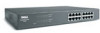
1 Introduction Dell™ PowerConnect™ 26xx switches provide 10/100/1000-Mbps Gigabit Ethernet connectivity. and 24-port switches • PowerConnect 26xx Switches CD • AC power cord Introduction 5 The switches have the following items: • Switch • Self-... wallmountable, standard 1U chassis • Internal power supply Package Contents Before you install a switch, verify that your package contains the following features: • 10/100/1000-Mbps switch ports - 8 ports (PowerConnect 2608) - 16 ports (PowerConnect 2616) - 24 ports, including one combination RJ...
1 Introduction Dell™ PowerConnect™ 26xx switches provide 10/100/1000-Mbps Gigabit Ethernet connectivity. and 24-port switches • PowerConnect 26xx Switches CD • AC power cord Introduction 5 The switches have the following items: • Switch • Self-... wallmountable, standard 1U chassis • Internal power supply Package Contents Before you install a switch, verify that your package contains the following features: • 10/100/1000-Mbps switch ports - 8 ports (PowerConnect 2608) - 16 ports (PowerConnect 2616) - 24 ports, including one combination RJ...
User's Guide
Page 6
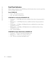
... Collisions are occurring on . 10/100/1000 Ports Link/Activity (SPD/LNK/ACT) LED • Steady green - www.dell.com | support.dell.com Front Panel Indicators All 26xx switches contain two rows of LEDS that provide information about connection speed, data activity, and ...duplex operation mode. The port is being transmitted or received. • Blinking green - Power (POWER) LED • Green - The switch is being transmitted...
... Collisions are occurring on . 10/100/1000 Ports Link/Activity (SPD/LNK/ACT) LED • Steady green - www.dell.com | support.dell.com Front Panel Indicators All 26xx switches contain two rows of LEDS that provide information about connection speed, data activity, and ...duplex operation mode. The port is being transmitted or received. • Blinking green - Power (POWER) LED • Green - The switch is being transmitted...
User's Guide
Page 8
www.dell.com | support.dell.com Figure 1-3. All ports can connect directly to a device that Category 5E (CAT 5E) cabling is more than 100 meters away. SFP Port On the ... to Each Other Each port supports Auto MDI and MDIX functionality. However, using the SFP port disables the RJ-45 connector of the switch. PowerConnect 2624 power LED FDX/HDX LEDs SPD/LNK/ACT LEDs RJ-45 ports Connecting Devices SFP port RJ-45 Switch Ports RJ-45 connectors are located on...
www.dell.com | support.dell.com Figure 1-3. All ports can connect directly to a device that Category 5E (CAT 5E) cabling is more than 100 meters away. SFP Port On the ... to Each Other Each port supports Auto MDI and MDIX functionality. However, using the SFP port disables the RJ-45 connector of the switch. PowerConnect 2624 power LED FDX/HDX LEDs SPD/LNK/ACT LEDs RJ-45 ports Connecting Devices SFP port RJ-45 Switch Ports RJ-45 connectors are located on...
User's Guide
Page 10
... cm (19 inches). Allow at least 5.1 cm (2 inches) on each side for proper ventilation and 12.7 cm (5 inches) at the back for power cable clearance. 2 Attach rubber feet on the bottom of the switch (see Figure 1-5). 10 Introduction NOTE: Do not install rubber feet on the flat ... are recommended to cable connectors. Installing the Switch on a Flat Surface The switch can be installed on a flat surface. www.dell.com | support.dell.com Mounting Kit Instructions These switches come with mounting brackets and screws for rackmounting or wallmounting and rubber feet for stationing on any ...
... cm (19 inches). Allow at least 5.1 cm (2 inches) on each side for proper ventilation and 12.7 cm (5 inches) at the back for power cable clearance. 2 Attach rubber feet on the bottom of the switch (see Figure 1-5). 10 Introduction NOTE: Do not install rubber feet on the flat ... are recommended to cable connectors. Installing the Switch on a Flat Surface The switch can be installed on a flat surface. www.dell.com | support.dell.com Mounting Kit Instructions These switches come with mounting brackets and screws for rackmounting or wallmounting and rubber feet for stationing on any ...
User's Guide
Page 11
... locate the switch where there may be located in the rack. 4 Insert and tighten two screws appropriate for your rack requires them. Figure 1-5. Brackets for power cable clearance. • The location must not be data or electrical cabling located directly behind the unit. • The...
... locate the switch where there may be located in the rack. 4 Insert and tighten two screws appropriate for your rack requires them. Figure 1-5. Brackets for power cable clearance. • The location must not be data or electrical cabling located directly behind the unit. • The...
User's Guide
Page 12
one SFP connector available on 24-port switch Power Supply 100-240 VAC/5060 Hz universal input 12 Introduction Brackets for Wall Installation 3 Place the switch against the wall and mark the ....3 10Base-T IEEE 802.3u 100Base-TX IEEE 802.3z/ab 1000Base-T IEEE 802.3x Flow Control IEEE 802.3p Priority Interface RJ-45 connectors; www.dell.com | support.dell.com Figure 1-6.
one SFP connector available on 24-port switch Power Supply 100-240 VAC/5060 Hz universal input 12 Introduction Brackets for Wall Installation 3 Place the switch against the wall and mark the ....3 10Base-T IEEE 802.3u 100Base-TX IEEE 802.3z/ab 1000Base-T IEEE 802.3x Flow Control IEEE 802.3p Priority Interface RJ-45 connectors; www.dell.com | support.dell.com Figure 1-6.
User's Guide
Page 15
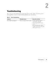
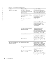
Basic Troubleshooting Problem Probable Cause Power LED is securely connected to the switch and to the switch. There is connected to a properly functioning and active power source. Ensure that the switch is no power to a power source. Corrective Action Confirm that the power cable is not lighted. Troubleshooting 15 Table 2-1. Table 2-1 describes general cluster problems you may encounter and the probable causes and solutions. 2 Troubleshooting This section provides troubleshooting information for your switch.
Basic Troubleshooting Problem Probable Cause Power LED is securely connected to the switch and to the switch. There is connected to a properly functioning and active power source. Ensure that the switch is no power to a power source. Corrective Action Confirm that the power cable is not lighted. Troubleshooting 15 Table 2-1. Table 2-1 describes general cluster problems you may encounter and the probable causes and solutions. 2 Troubleshooting This section provides troubleshooting information for your switch.
User's Guide
Page 16
...inserted into the ports of the switch and the attached device. The attached device is not configured correctly, or it is not powered on the attached device is not securely connected to automatically detect and set port speed and duplex settings. Try a known working ... 568B standards. Move the connected device closer to the switch and use a shorter cable. 16 Troubleshooting Bad switch port. www.dell.com | support.dell.com Table 2-1. Basic Troubleshooting (continued) Problem Probable Cause Link LED is damaged or not properly terminated. The cable is operating properly...
...inserted into the ports of the switch and the attached device. The attached device is not configured correctly, or it is not powered on the attached device is not securely connected to automatically detect and set port speed and duplex settings. Try a known working ... 568B standards. Move the connected device closer to the switch and use a shorter cable. 16 Troubleshooting Bad switch port. www.dell.com | support.dell.com Table 2-1. Basic Troubleshooting (continued) Problem Probable Cause Link LED is damaged or not properly terminated. The cable is operating properly...
User's Guide
Page 21
... your invoice or packing slip available when you need information about Dell hardware. Technical Support Service Dell's technical support service is available; see the contact information for customer assistance. This service may not be returned in all items being returned (such as power cables, media such as CDs and diskettes, and guides) if...
... your invoice or packing slip available when you need information about Dell hardware. Technical Support Service Dell's technical support service is available; see the contact information for customer assistance. This service may not be returned in all items being returned (such as power cables, media such as CDs and diskettes, and guides) if...


