User's Guide
Page 10
... feet are optional, but are rackmounting the switch. It can also be installed on the bottom of the chassis. www.dell.com | support.dell.com Mounting Kit Instructions These switches come with mounting brackets and screws for rackmounting or wallmounting and rubber feet for stationing on the flat surface and check for proper ventilation. To...
... feet are optional, but are rackmounting the switch. It can also be installed on the bottom of the chassis. www.dell.com | support.dell.com Mounting Kit Instructions These switches come with mounting brackets and screws for rackmounting or wallmounting and rubber feet for stationing on the flat surface and check for proper ventilation. To...
User's Guide
Page 11
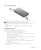
...; Allow at least 5.1 cm (2 inches) on a wall, complete the following steps: 1 Ensure that have threaded mounting holes. 3 Position the switch in the rack and align the holes in the mounting bracket with the holes in the rack. 4 Insert and tighten two screws appropriate for power cable clearance. • The... cabling located directly behind the unit. • The power cable must reach an outlet. 2 Use the supplied screws to attach a mounting bracket to each side for proper ventilation and 12.7 cm (5 inches) at the back for your rack requires them. Introduction 11 Figure 1-5.
...; Allow at least 5.1 cm (2 inches) on a wall, complete the following steps: 1 Ensure that have threaded mounting holes. 3 Position the switch in the rack and align the holes in the mounting bracket with the holes in the rack. 4 Insert and tighten two screws appropriate for power cable clearance. • The... cabling located directly behind the unit. • The power cable must reach an outlet. 2 Use the supplied screws to attach a mounting bracket to each side for proper ventilation and 12.7 cm (5 inches) at the back for your rack requires them. Introduction 11 Figure 1-5.
User's Guide
Page 12
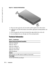
... the against the wall so that the bracket holes align with the holes in the wall. 6 Insert and tighten the screws through each of the mounting brackets. one SFP connector available on 24-port switch Power Supply 100-240 VAC/5060 Hz universal input 12 Introduction www.dell.com | support.dell.com Figure 1-6.
... the against the wall so that the bracket holes align with the holes in the wall. 6 Insert and tighten the screws through each of the mounting brackets. one SFP connector available on 24-port switch Power Supply 100-240 VAC/5060 Hz universal input 12 Introduction www.dell.com | support.dell.com Figure 1-6.