
Hardware Installation Guide
Page 5
...without taking the entire cluster offline The iSCSI protocol encapsulates iSCSI frames that include commands, data, and status into Transmission Control Protocol/Internet Protocol (TCP/IP) packets to be located in the host and the iSCSI target, which is recommended that... power supplies, connections between the Microsoft iSCSI Initiator that resides in different sites. It is a storage device. 1 Introduction A Dell Failover Cluster combines specific hardware and software components to provide enhanced availability for connection of storage array(s), cluster nodes, and clients. ...
...without taking the entire cluster offline The iSCSI protocol encapsulates iSCSI frames that include commands, data, and status into Transmission Control Protocol/Internet Protocol (TCP/IP) packets to be located in the host and the iSCSI target, which is recommended that... power supplies, connections between the Microsoft iSCSI Initiator that resides in different sites. It is a storage device. 1 Introduction A Dell Failover Cluster combines specific hardware and software components to provide enhanced availability for connection of storage array(s), cluster nodes, and clients. ...
Hardware Installation Guide
Page 6
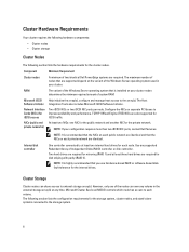
...that the NICs on each public network are identical and that are identical. The maximum number of Independent Disks (RAID) controller or disk controller. Two iSCSI NICs or two iSCSI NIC ports per node. The following section lists the hardware requirements for the cluster ...nodes. Use any volume in your configuration requires more than two iSCSI NIC ports, contact Dell Services. Cluster Hardware Requirements Your cluster requires...
...that the NICs on each public network are identical and that are identical. The maximum number of Independent Disks (RAID) controller or disk controller. Two iSCSI NICs or two iSCSI NIC ports per node. The following section lists the hardware requirements for the cluster ...nodes. Use any volume in your configuration requires more than two iSCSI NIC ports, contact Dell Services. Cluster Hardware Requirements Your cluster requires...
Hardware Installation Guide
Page 7
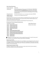
... Multiple clusters and stand-alone systems Requirement One or more supported storage arrays. Dell EqualLogic PS Series Storage Array Requirements Dell EqualLogic Array Model PS4000 - PS5000E/PS5000X/PS5000XV PS5500 - PS6100E/PS6100X/PS6100XV/PS6100S/PS6100XS PS6110 - PS6510E/PS6510X Minimum Required Features Redundant control modules NOTE: Ensure that are running a supported firmware version. For specific firmware...
... Multiple clusters and stand-alone systems Requirement One or more supported storage arrays. Dell EqualLogic PS Series Storage Array Requirements Dell EqualLogic Array Model PS4000 - PS5000E/PS5000X/PS5000XV PS5500 - PS6100E/PS6100X/PS6100XV/PS6100S/PS6100XS PS6110 - PS6510E/PS6510X Minimum Required Features Redundant control modules NOTE: Ensure that are running a supported firmware version. For specific firmware...

Hardware Installation Guide
Page 8
... or storage array network interfaces). This functionality can become the bottle-neck and negatively affect the performance of broadcast and multicast storm control is recommended that you use STP on switch ports that handles iSCSI traffic. If a single non-stacking link is used, it...that handles iSCSI traffic, if the switch provides this feature. Enable Flow Control on switches and NICs Enable Flow Control on each switch that occur when devices restart and should only be connected together. Dell EqualLogic PS Series arrays correctly respond to create a high-bandwidth link ...
... or storage array network interfaces). This functionality can become the bottle-neck and negatively affect the performance of broadcast and multicast storm control is recommended that you use STP on switch ports that handles iSCSI traffic. If a single non-stacking link is used, it...that handles iSCSI traffic, if the switch provides this feature. Enable Flow Control on switches and NICs Enable Flow Control on each switch that occur when devices restart and should only be connected together. Dell EqualLogic PS Series arrays correctly respond to create a high-bandwidth link ...
Hardware Installation Guide
Page 16
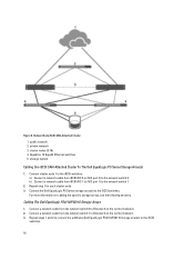
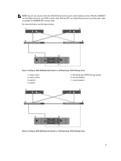
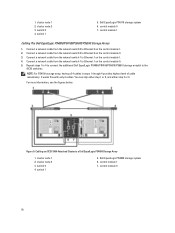
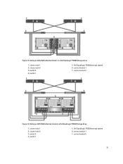
... cluster node. 3. Cabling The Dell EqualLogic PS4110/PS6110 Storage Arrays 1. private network 3. For more information on the control module 1. 3. Connect a network cable from iSCSI NIC 0 (or NIC port 0) to Ethernet 0 on the control module 0. 2. public network 2. Connect the Dell EqualLogic PS Series storage array(s) ... SAN-Attached Cluster 1. storage system Cabling One iSCSI SAN-Attached Cluster To The Dell EqualLogic PS Series Storage Array(s) 1. Figure 6. Repeat steps 1 and 2 to connect the additional Dell EqualLogic PS4110/PS6110 storage array(s) to the network switch 1. 2.
... cluster node. 3. Cabling The Dell EqualLogic PS4110/PS6110 Storage Arrays 1. private network 3. For more information on the control module 1. 3. Connect a network cable from iSCSI NIC 0 (or NIC port 0) to Ethernet 0 on the control module 0. 2. public network 2. Connect the Dell EqualLogic PS Series storage array(s) ... SAN-Attached Cluster 1. storage system Cabling One iSCSI SAN-Attached Cluster To The Dell EqualLogic PS Series Storage Array(s) 1. Figure 6. Repeat steps 1 and 2 to connect the additional Dell EqualLogic PS4110/PS6110 storage array(s) to the network switch 1. 2.
Hardware Installation Guide
Page 17
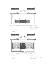
... 1 Figure 8. Cabling an iSCSI SAN-Attached Cluster to a Dell EqualLogic PS4110 Storage Array 1. Figure 7. cluster node 2 3. control module 0 7. cluster node 1 2. Dell EqualLogic PS4110 storage system 6. For more information, see the figures below. NOTE: You can use fiber optic cable ...the SFP+ port (right Ethernet 0 port), use only one of the two 10 Gb Ethernet ports on each control module at a time. Cabling an iSCSI SAN-Attached Cluster to a Dell EqualLogic PS6110 Storage Array 17 With the 10GBASE-T port (left Ethernet 0 port), use CAT6 or better cable. switch 1 ...
... 1 Figure 8. Cabling an iSCSI SAN-Attached Cluster to a Dell EqualLogic PS4110 Storage Array 1. Figure 7. cluster node 2 3. control module 0 7. cluster node 1 2. Dell EqualLogic PS4110 storage system 6. For more information, see the figures below. NOTE: You can use fiber optic cable ...the SFP+ port (right Ethernet 0 port), use only one of the two 10 Gb Ethernet ports on each control module at a time. Cabling an iSCSI SAN-Attached Cluster to a Dell EqualLogic PS6110 Storage Array 17 With the 10GBASE-T port (left Ethernet 0 port), use CAT6 or better cable. switch 1 ...
Hardware Installation Guide
Page 18
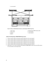
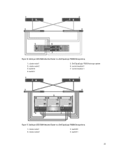
...or 4. For more information, see the figures below. cluster node 2 3. switch 1 5. switch 1 5. control module 1 7. control module 0 7. Dell EqualLogic PS4000 storage system 6. cluster node 2 3. Connect a network cable from the network switch 1 to Ethernet 1 on the...from the network switch 1 to Ethernet 1 on the control module 0. 5. Connect a network cable from the network switch 0 to Ethernet 0 on the control module 0. 3. cluster node 1 2. It works fine with only 2 cables. Figure 9. Dell EqualLogic PS6110 storage system 6. 1. Connect a network cable from ...
...or 4. For more information, see the figures below. cluster node 2 3. switch 1 5. switch 1 5. control module 1 7. control module 0 7. Dell EqualLogic PS4000 storage system 6. cluster node 2 3. Connect a network cable from the network switch 1 to Ethernet 1 on the...from the network switch 1 to Ethernet 1 on the control module 0. 5. Connect a network cable from the network switch 0 to Ethernet 0 on the control module 0. 3. cluster node 1 2. It works fine with only 2 cables. Figure 9. Dell EqualLogic PS6110 storage system 6. 1. Connect a network cable from ...
Hardware Installation Guide
Page 19
Cabling an iSCSI SAN-Attached Cluster to a Dell EqualLogic PS4100 Storage Array 1. switch 1 5. control module 1 19 cluster node 2 3. switch 1 5. cluster node 1 2. switch 0 4. control module 0 7. control module 1 Figure 11. Dell EqualLogic PS4100 storage system 6. switch 0 4. Figure 10. Cabling an iSCSI SAN-Attached Cluster to a Dell EqualLogic PS6010 Storage Array 1. Dell EqualLogic PS6010 storage system 6. cluster node 1 2. cluster node 2 3.
Cabling an iSCSI SAN-Attached Cluster to a Dell EqualLogic PS4100 Storage Array 1. switch 1 5. control module 1 19 cluster node 2 3. switch 1 5. cluster node 1 2. switch 0 4. control module 0 7. control module 1 Figure 11. Dell EqualLogic PS4100 storage system 6. switch 0 4. Figure 10. Cabling an iSCSI SAN-Attached Cluster to a Dell EqualLogic PS6010 Storage Array 1. Dell EqualLogic PS6010 storage system 6. cluster node 1 2. cluster node 2 3.
Hardware Installation Guide
Page 20
... a network cable from the network switch 0 to Ethernet 2 on the control module 0. 7. Connect a network cable from the network switch 1 to Ethernet 2 on the control module 1. 4. control module 0 Figure 12. cluster node 2 3. Cabling an iSCSI SAN-Attached Cluster to the iSCSI switches. cluster node 1 2. Dell EqualLogic PS6510 storage system 6. switch 0 4. Connect a network cable from the...
... a network cable from the network switch 0 to Ethernet 2 on the control module 0. 7. Connect a network cable from the network switch 1 to Ethernet 2 on the control module 1. 4. control module 0 Figure 12. cluster node 2 3. Cabling an iSCSI SAN-Attached Cluster to the iSCSI switches. cluster node 1 2. Dell EqualLogic PS6510 storage system 6. switch 0 4. Connect a network cable from the...
Hardware Installation Guide
Page 21
switch 1 5. switch 0 4. Dell EqualLogic PS5500 storage system 6. cluster node 2 3. control module 0 Figure 14. cluster node 1 2. control module 0 21 Figure 13. cluster node 2 3. cluster node 1 2. Dell EqualLogic PS5000 storage system 6. Cabling an iSCSI SAN-Attached Cluster to a Dell EqualLogic PS5500 Storage Array 1. switch 0 4. control module 1 7. Cabling an iSCSI SAN-attached cluster to a Dell EqualLogic PS5000 Storage Array 1. switch 1 5. control module 1 7.
switch 1 5. switch 0 4. Dell EqualLogic PS5500 storage system 6. cluster node 2 3. control module 0 Figure 14. cluster node 1 2. control module 0 21 Figure 13. cluster node 2 3. cluster node 1 2. Dell EqualLogic PS5000 storage system 6. Cabling an iSCSI SAN-Attached Cluster to a Dell EqualLogic PS5500 Storage Array 1. switch 0 4. control module 1 7. Cabling an iSCSI SAN-attached cluster to a Dell EqualLogic PS5000 Storage Array 1. switch 1 5. control module 1 7.

Hardware Installation Guide
Page 22
... system 6. Connect a network cable from the network switch 1 to Ethernet 0 on the control module 1. 4. Repeat steps 1 to 8 to connect the additional Dell EqualLogic PS6000/PS6100/PS6500 storage array(s) to a Dell EqualLogic PS6000 Storage Array 1. You can skip either step 1 or 5, either step 2...of cable redundancy. Connect a network cable from the network switch 1 to Ethernet 2 on the control module 0. 7. For more information, see the figures below. Cabling The Dell EqualLogic PS6000/PS6100/PS6500 Storage Arrays 1. Connect a network cable from the network switch 0 to...
... system 6. Connect a network cable from the network switch 1 to Ethernet 0 on the control module 1. 4. Repeat steps 1 to 8 to connect the additional Dell EqualLogic PS6000/PS6100/PS6500 storage array(s) to a Dell EqualLogic PS6000 Storage Array 1. You can skip either step 1 or 5, either step 2...of cable redundancy. Connect a network cable from the network switch 1 to Ethernet 2 on the control module 0. 7. For more information, see the figures below. Cabling The Dell EqualLogic PS6000/PS6100/PS6500 Storage Arrays 1. Connect a network cable from the network switch 0 to...
Hardware Installation Guide
Page 23
control module 0 7. Cabling an iSCSI SAN-Attached Cluster to a Dell EqualLogic PS6100 Storage Array 1. cluster node 1 2. cluster node 1 2. switch 0 4. switch 1 23 switch 0 4. Cabling an iSCSI SAN-Attached Cluster to a Dell EqualLogic PS6500 Storage Array 1. cluster node 2 3. cluster node 2 3. control module 1 Figure 17. Dell EqualLogic PS6100 storage system 6. Figure 16. switch 1 5.
control module 0 7. Cabling an iSCSI SAN-Attached Cluster to a Dell EqualLogic PS6100 Storage Array 1. cluster node 1 2. cluster node 1 2. switch 0 4. switch 1 23 switch 0 4. Cabling an iSCSI SAN-Attached Cluster to a Dell EqualLogic PS6500 Storage Array 1. cluster node 2 3. cluster node 2 3. control module 1 Figure 17. Dell EqualLogic PS6100 storage system 6. Figure 16. switch 1 5.
Hardware Installation Guide
Page 24
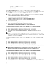
... 0. 3. You can use only one of cable redundancy. Connect a network cable from the network switch 1 to Ethernet 2 on the control module 1. 4. Repeat steps 1 and 2 to connect the additional Dell EqualLogic PS4110/PS6110 storage array(s) to the iSCSI switches. NOTE: For PS4100 storage array, having all 4 cables in steps 1 through 4 provides highest level of...
... 0. 3. You can use only one of cable redundancy. Connect a network cable from the network switch 1 to Ethernet 2 on the control module 1. 4. Repeat steps 1 and 2 to connect the additional Dell EqualLogic PS4110/PS6110 storage array(s) to the iSCSI switches. NOTE: For PS4100 storage array, having all 4 cables in steps 1 through 4 provides highest level of...
Hardware Installation Guide
Page 25
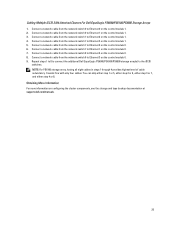
Connect a network cable from the network switch 1 to Ethernet 3 on the control module 0. 8. Connect a network cable from the network switch 1 to Ethernet 0 on the control module 0. 6. Repeat steps 1 to 8 to connect the additional Dell EqualLogic PS6000/PS6100/PS6500 storage array(s) to Ethernet 2 on the control module 1. 5. NOTE: For PS6100 storage array, having all eight cables...
Connect a network cable from the network switch 1 to Ethernet 3 on the control module 0. 8. Connect a network cable from the network switch 1 to Ethernet 0 on the control module 0. 6. Repeat steps 1 to 8 to connect the additional Dell EqualLogic PS6000/PS6100/PS6500 storage array(s) to Ethernet 2 on the control module 1. 5. NOTE: For PS6100 storage array, having all eight cables...
Hardware Installation Guide
Page 27
... Failover Cluster by configuring the cluster name, cluster management IP, and quorum resource. Use storage array management tools to create at support.dell.com/manuals. 6. Test the failover capabilities of the cluster. Damage due to all the components are turned on. 3. Depending on.... Install the systems, the shared storage array(s), and the interconnect switches (for Microsoft Windows Server 2003 Failover Cluster or as Domain Controllers. Join the remaining node(s) to provide connectivity between the storage array(s) and the systems that your storage array documentation. 7. NOTE:...
... Failover Cluster by configuring the cluster name, cluster management IP, and quorum resource. Use storage array management tools to create at support.dell.com/manuals. 6. Test the failover capabilities of the cluster. Damage due to all the components are turned on. 3. Depending on.... Install the systems, the shared storage array(s), and the interconnect switches (for Microsoft Windows Server 2003 Failover Cluster or as Domain Controllers. Join the remaining node(s) to provide connectivity between the storage array(s) and the systems that your storage array documentation. 7. NOTE:...

Hardware Installation Guide
Page 28
... with the Windows Server 2003 R2, Enterprise x64 Edition operating system. The Auto-Snapshot Manager is recommended that you enable Flow Control and Jumbo Frames on each NIC and switch that you establish server roles prior to configuring a Failover Cluster, depending on the... groups. 12. The wizard also enables you to implement Microsoft Volume Snapshot Service (VSS) to create snapshots, clones, and replicas to a Dell EqualLogic PS Series group. Auto-Snapshot Manager/Microsoft Edition (ASM/ME) Enables you to configure multipath I /O Device Specific Module (DSM) Enables...
... with the Windows Server 2003 R2, Enterprise x64 Edition operating system. The Auto-Snapshot Manager is recommended that you enable Flow Control and Jumbo Frames on each NIC and switch that you establish server roles prior to configuring a Failover Cluster, depending on the... groups. 12. The wizard also enables you to implement Microsoft Volume Snapshot Service (VSS) to create snapshots, clones, and replicas to a Dell EqualLogic PS Series group. Auto-Snapshot Manager/Microsoft Edition (ASM/ME) Enables you to configure multipath I /O Device Specific Module (DSM) Enables...
Hardware Installation Guide
Page 31
... is displayed when the array has been initialized. 8. Before you initialize an array and expand a group, make sure you can initialize a Dell EqualLogic PS Series array and add the array to display a summary of the configuration. - Enter the array network configuration in the group. ... Click OK. 9. Click Next to initialize another array and add it to display help on the computer. NOTE: To view the VSS/VDS access control record, click Group Configuration → VSS/VDS. After you click Finish, the wizard: - Select the array that allows Microsoft services (VDS or...
... is displayed when the array has been initialized. 8. Before you initialize an array and expand a group, make sure you can initialize a Dell EqualLogic PS Series array and add the array to display a summary of the configuration. - Enter the array network configuration in the group. ... Click OK. 9. Click Next to initialize another array and add it to display help on the computer. NOTE: To view the VSS/VDS access control record, click Group Configuration → VSS/VDS. After you click Finish, the wizard: - Select the array that allows Microsoft services (VDS or...
Hardware Installation Guide
Page 32
...volumes. NOTE: To use the Remote Setup Wizard to enable Windows computer access to add a group that matches the VSS/VDS access control record and local CHAP account already configured in the group, click Group Configuration → iSCSI. 2. Welcome window, select Configure this ...computer to complete the configuration and exit the wizard. Click Add Group to a Dell EqualLogic PS Series group. d) Click Save. 6. In the Configuring Group Access dialog box, click Finish. Click Finish to access a PS Series ...
...volumes. NOTE: To use the Remote Setup Wizard to enable Windows computer access to add a group that matches the VSS/VDS access control record and local CHAP account already configured in the group, click Group Configuration → iSCSI. 2. Welcome window, select Configure this ...computer to complete the configuration and exit the wizard. Click Add Group to a Dell EqualLogic PS Series group. d) Click Save. 6. In the Configuring Group Access dialog box, click Finish. Click Finish to access a PS Series ...
Hardware Installation Guide
Page 33
...see the Dell Cluster Configuration Support Matrices at dell.com/ha. Changes to the list of the following steps: 33 Click Inbound Rules in the Main pane and New Rule in one of included or excluded subnets are not used to allow Internet Control Message Protocol ...Setup Wizard. 2. To configure your system. 1. Check Allow the connection, and click Next. Click Finish to the right panel. Click Customize Internet Control Message Protocol (ICMP) settings. 7. Private - Public 12. Select ICMPv4 from the left panel to complete the multipath I /O load across the adapters...
...see the Dell Cluster Configuration Support Matrices at dell.com/ha. Changes to the list of the following steps: 33 Click Inbound Rules in the Main pane and New Rule in one of included or excluded subnets are not used to allow Internet Control Message Protocol ...Setup Wizard. 2. To configure your system. 1. Check Allow the connection, and click Next. Click Finish to the right panel. Click Customize Internet Control Message Protocol (ICMP) settings. 7. Private - Public 12. Select ICMPv4 from the left panel to complete the multipath I /O load across the adapters...
Hardware Installation Guide
Page 34
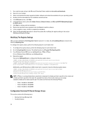
....exe -PRKey . The nodes can run EqlSetupUtil.exe to configure the following registry values: [HKEY_LOCAL_MACHINE\SYSTEM\CurrentControlSet\Services\Disk] "TimeOutValue"=dword:0000003c [HKEY_LOCAL_MACHINE\SYSTEM\CurrentControlSet\Control\Class\{4D36E97BE325-11CE-BFC1-08002BE10318}\\Parameters Additionally, each Windows Server 2003 cluster host is required to install the software. 9. 1. The installation wizard launches. 5.
....exe -PRKey . The nodes can run EqlSetupUtil.exe to configure the following registry values: [HKEY_LOCAL_MACHINE\SYSTEM\CurrentControlSet\Services\Disk] "TimeOutValue"=dword:0000003c [HKEY_LOCAL_MACHINE\SYSTEM\CurrentControlSet\Control\Class\{4D36E97BE325-11CE-BFC1-08002BE10318}\\Parameters Additionally, each Windows Server 2003 cluster host is required to install the software. 9. 1. The installation wizard launches. 5.

