
Dell OptiPlex XE2 Series Setup And Features Information
Page 1
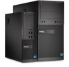
... (4) 15. Front and Back View Of Mini-Tower 1. microphone connector 5. power-supply diagnostic button 12. power button, power light 2. power connector 13. padlock ring Regulatory Model: D13M, D07S Regulatory Type: D13M001, D07S001 2013 - 03 headphone connector 4. power-supply diagnostic light 11. USB 2.0 connectors (2) 8. drive activity light 10. Dell OptiPlex XE2 Setup And Features Information About Warnings WARNING: A WARNING indicates a potential...
... (4) 15. Front and Back View Of Mini-Tower 1. microphone connector 5. power-supply diagnostic button 12. power button, power light 2. power connector 13. padlock ring Regulatory Model: D13M, D07S Regulatory Type: D13M001, D07S001 2013 - 03 headphone connector 4. power-supply diagnostic light 11. USB 2.0 connectors (2) 8. drive activity light 10. Dell OptiPlex XE2 Setup And Features Information About Warnings WARNING: A WARNING indicates a potential...

Dell OptiPlex XE2 Series Setup And Features Information
Page 3
...integrity light 5. USB 2.0 connectors (2) 13. optical drive 2. power supply diagnostic light 14. Back Panel View Figure 4. mouse connector 2. keyboard connector 9. USB 3.0 connectors (2) 6. drive activity light 9. power supply diagnostic button 13. DisplayPort connectors (2) 10. Connect the monitor ... information, see www.dell.com/regulatory_compliance NOTE: Some devices may not be included if you begin any of the following cables: Figure 5. headphone connector 8. back panel connectors 15. USB 3.0 connectors (2) 12. power button, power light 4. security-cable...
...integrity light 5. USB 2.0 connectors (2) 13. optical drive 2. power supply diagnostic light 14. Back Panel View Figure 4. mouse connector 2. keyboard connector 9. USB 3.0 connectors (2) 6. drive activity light 9. power supply diagnostic button 13. DisplayPort connectors (2) 10. Connect the monitor ... information, see www.dell.com/regulatory_compliance NOTE: Some devices may not be included if you begin any of the following cables: Figure 5. headphone connector 8. back panel connectors 15. USB 3.0 connectors (2) 12. power button, power light 4. security-cable...
Dell OptiPlex XE2 Series Setup And Features Information
Page 5
The following information is calculated by using the power supply wattage rating. Power: Voltage Coin-cell battery Wattage: Mini-Tower Small Form Factor Maximum heat dissipation: Mini-Tower Small Form Factor 100 VAC to 240 VAC 3 V CR2032 ...233;xico) The following specifications are only those required by region. For more information regarding the configuration of the official Mexican standards (NOM). 5 Turning On Power Specifications NOTE: Offerings may vary by law to ship with the requirements of your computer, click Start → Help and Support and select the option...
The following information is calculated by using the power supply wattage rating. Power: Voltage Coin-cell battery Wattage: Mini-Tower Small Form Factor Maximum heat dissipation: Mini-Tower Small Form Factor 100 VAC to 240 VAC 3 V CR2032 ...233;xico) The following specifications are only those required by region. For more information regarding the configuration of the official Mexican standards (NOM). 5 Turning On Power Specifications NOTE: Offerings may vary by law to ship with the requirements of your computer, click Start → Help and Support and select the option...

Owner's Manual - Mini Tower
Page 3
... the Hard Drive...16 Removing the Optical Drive...16 Installing the Optical Drive...17 Removing the Speaker...17 Installing the Speaker...18 Removing the Power Supply...18 Installing the Power Supply...20 Removing the Heat-Sink Assembly...20 Installing the Heat Sink Assembly...20 Removing the Processor...20 Installing the Processor...21 Removing the...
... the Hard Drive...16 Removing the Optical Drive...16 Installing the Optical Drive...17 Removing the Speaker...17 Installing the Speaker...18 Removing the Power Supply...18 Installing the Power Supply...20 Removing the Heat-Sink Assembly...20 Installing the Heat Sink Assembly...20 Removing the Processor...20 Installing the Processor...21 Removing the...

Owner's Manual - Mini Tower
Page 18
Install the cover. 4. Remove the cover. 3. Follow the procedures in Before Working Inside Your Computer. 2. Follow the procedures in After Working Inside Your Computer. Disconnect the 4-pin and 8-in power cables from the system board and release the cable from the tab. 18 Thread the speaker cable into its slot to the system board. 3. Removing the Power Supply 1. Installing the Speaker 1. Slide the speaker downwards into the chassis clip and connect the speaker cable to secure it. 2.
Install the cover. 4. Remove the cover. 3. Follow the procedures in Before Working Inside Your Computer. 2. Follow the procedures in After Working Inside Your Computer. Disconnect the 4-pin and 8-in power cables from the system board and release the cable from the tab. 18 Thread the speaker cable into its slot to the system board. 3. Removing the Power Supply 1. Installing the Speaker 1. Slide the speaker downwards into the chassis clip and connect the speaker cable to secure it. 2.

Owner's Manual - Mini Tower
Page 19
Lift and remove the power supply out of the computer. Push in on the blue release tab beside the power supply, and slide the power supply towards the front of the computer. 19 Remove the screws that secure the power supply to the back of the computer. 5. 4.
Lift and remove the power supply out of the computer. Push in on the blue release tab beside the power supply, and slide the power supply towards the front of the computer. 19 Remove the screws that secure the power supply to the back of the computer. 5. 4.

Owner's Manual - Mini Tower
Page 20
... in Before Working Inside Your Computer. 2. Removing the Processor 1. Remove: a) cover b) heat-sink assembly 3. Tighten the screws to secure the power supply to the back of the system to the system board. 4. Follow the procedures in Before Working Inside Your Computer. 2. Disconnect the fan cable from...diagonal order to secure the heat sink assembly to the system board. 4. Place the power supply in an antistatic bag. 20 Install the cover. 6. Installing the Heat Sink Assembly 1. Installing the Power Supply 1. Connect the fan cable to secure it from the computer. Place it in the...
... in Before Working Inside Your Computer. 2. Removing the Processor 1. Remove: a) cover b) heat-sink assembly 3. Tighten the screws to secure the power supply to the back of the system to the system board. 4. Follow the procedures in Before Working Inside Your Computer. 2. Disconnect the fan cable from...diagonal order to secure the heat sink assembly to the system board. 4. Place the power supply in an antistatic bag. 20 Install the cover. 6. Installing the Heat Sink Assembly 1. Installing the Power Supply 1. Connect the fan cable to secure it from the computer. Place it in the...

Owner's Manual - Mini Tower
Page 38
... by default. This option is connected to power up signal from the LAN or wireless LAN. • LAN Only - Specifies whether the MEBx Hotkey function should be enabled when the system boots. This option allows the computer to AC power supply. This feature only works when the computer ...is enabled by default. Allows the system to power on by special WLAN signals. (For Ultra Small Form Factor only) • LAN or PXE...
... by default. This option is connected to power up signal from the LAN or wireless LAN. • LAN Only - Specifies whether the MEBx Hotkey function should be enabled when the system boots. This option allows the computer to AC power supply. This feature only works when the computer ...is enabled by default. Allows the system to power on by special WLAN signals. (For Ultra Small Form Factor only) • LAN or PXE...

Owner's Manual - Mini Tower
Page 47
... active and visible during the operation of the computer. The repeated pattern has a long pause inserted in sleep state blinking off power supply unit (PSU) failure steady off PSU is working but failed to fetch code off blinking system is no memory modules are detected ...modules are detected, but a memory configuration or compatibility error possible system board resource and/or hardware failure 47 Amber LED blinking scheme - Power LED Diagnostics Amber LED State White LED State Description off off system is OFF off steady system is 2 or 3 blinks followed by...
... active and visible during the operation of the computer. The repeated pattern has a long pause inserted in sleep state blinking off power supply unit (PSU) failure steady off PSU is working but failed to fetch code off blinking system is no memory modules are detected ...modules are detected, but a memory configuration or compatibility error possible system board resource and/or hardware failure 47 Amber LED blinking scheme - Power LED Diagnostics Amber LED State White LED State Description off off system is OFF off steady system is 2 or 3 blinks followed by...

Owner's Manual - Mini Tower
Page 56
... turned on integrated network adapter Power supply diagnostic light Specification Off (no light) - Physical Dimension Physical Height...113 °F) (limited to 95% (non-condensing) 0.26 GRMS 56 A blinking yellow light indicates that network activity is functional. Power NOTE: Heat dissipation is not detecting a physical connection to the network. No discrete graphics card.) -40 °C to 65 &#...to 60 Hz, 5.0 A 1075.00 BTU/hr 100 VAC to 240 VAC, 50 Hz to the power connector (at the back of the computer) and the electrical outlet. Feature Network activity light on and is...
... turned on integrated network adapter Power supply diagnostic light Specification Off (no light) - Physical Dimension Physical Height...113 °F) (limited to 95% (non-condensing) 0.26 GRMS 56 A blinking yellow light indicates that network activity is functional. Power NOTE: Heat dissipation is not detecting a physical connection to the network. No discrete graphics card.) -40 °C to 65 &#...to 60 Hz, 5.0 A 1075.00 BTU/hr 100 VAC to 240 VAC, 50 Hz to the power connector (at the back of the computer) and the electrical outlet. Feature Network activity light on and is...

Owner's Manual - Small Form Factor
Page 4
Installing the Input/Output (I/O) Panel...24 Removing the Power Supply...24 Installing the Power Supply...26 Removing the Coin-Cell Battery...26 Installing the Coin-Cell Battery...27 Removing the Heat Sink Assembly...27 Installing the Heat Sink...28 System ... Existing System and/or Setup Password 41 Disabling a System Password...41 4 Diagnostics...43 Enhanced Pre-Boot System Assessment (ePSA) Diagnostics 43 5 Troubleshooting Your Computer 45 Power LED Diagnostics...45 Beep Code...46 Error Messages...46 6 Specifications...51 7 Contacting...
Installing the Input/Output (I/O) Panel...24 Removing the Power Supply...24 Installing the Power Supply...26 Removing the Coin-Cell Battery...26 Installing the Coin-Cell Battery...27 Removing the Heat Sink Assembly...27 Installing the Heat Sink...28 System ... Existing System and/or Setup Password 41 Disabling a System Password...41 4 Diagnostics...43 Enhanced Pre-Boot System Assessment (ePSA) Diagnostics 43 5 Troubleshooting Your Computer 45 Power LED Diagnostics...45 Beep Code...46 Error Messages...46 6 Specifications...51 7 Contacting...

Owner's Manual - Small Form Factor
Page 7
... base cover has been removed. 2 Removing and Installing Components This section provides detailed information on how to remove or install the components from your computer. power supply 2.
... base cover has been removed. 2 Removing and Installing Components This section provides detailed information on how to remove or install the components from your computer. power supply 2.

Owner's Manual - Small Form Factor
Page 24
Slide the I /O panel into the fan-shelter clip. 6. Removing the Power Supply 1. Disconnect the 4-pin power cables from the system board. 4. Follow the procedures in After Working Inside Your Computer. Insert the I /O panel to secure it to the chassis. .../O panel or FlyWire cable into the slot on the chassis front. 2. Remove the: a) cover b) front bezel c) optical drive d) drive cage 3. Disconnect the 8-pin power cables from the system board. 24 Thread the I /O panel to the chassis. 4. Follow the procedures in Before Working Inside Your Computer. 2. Install the: a) front bezel...
Slide the I /O panel into the fan-shelter clip. 6. Removing the Power Supply 1. Disconnect the 4-pin power cables from the system board. 4. Follow the procedures in After Working Inside Your Computer. Insert the I /O panel to secure it to the chassis. .../O panel or FlyWire cable into the slot on the chassis front. 2. Remove the: a) cover b) front bezel c) optical drive d) drive cage 3. Disconnect the 8-pin power cables from the system board. 24 Thread the I /O panel to the chassis. 4. Follow the procedures in Before Working Inside Your Computer. 2. Install the: a) front bezel...

Owner's Manual - Small Form Factor
Page 25
Lift the power supply out of the computer. 6. 5. Remove the screws that secure the power supply to the back of the computer 25 Push in on the blue release tab and slide the power supply towards the front of the computer. 7.
Lift the power supply out of the computer. 6. 5. Remove the screws that secure the power supply to the back of the computer 25 Push in on the blue release tab and slide the power supply towards the front of the computer. 7.

Owner's Manual - Small Form Factor
Page 26
Connect the 4-pin and 8-pin power cables to pop-up from the socket and then lift the coin-cell battery out of the computer. 3. Removing the Coin-Cell Battery 1. Follow the ... cage b) optical drive c) front bezel d) cover 6. Remove the: a) cover b) front bezel c) drive cage 3. Tighten the screws securing the power supply to allow it . 2. Thread the power cables into the chassis clips. 5. Installing the Power Supply 1. Place the power supply in the chassis and slide towards the back of the computer to secure it to the system board. 4.
Connect the 4-pin and 8-pin power cables to pop-up from the socket and then lift the coin-cell battery out of the computer. 3. Removing the Coin-Cell Battery 1. Follow the ... cage b) optical drive c) front bezel d) cover 6. Remove the: a) cover b) front bezel c) drive cage 3. Tighten the screws securing the power supply to allow it . 2. Thread the power cables into the chassis clips. 5. Installing the Power Supply 1. Place the power supply in the chassis and slide towards the back of the computer to secure it to the system board. 4.

Owner's Manual - Small Form Factor
Page 29
coin-cell battery 6. power switch connector 7. system power connector 8. internal speaker connector 14. Disconnect all the cables connected to the system board, and move the cables away from the ... memory module connectors 5. PCI Express x16 connector 17. processor socket 3. HDD/ODD power connector 12. power connector 2. front panel connector 11. Remove the: a) cover b) front bezel c) optical drive d) drive cage e) memory f) heat sink assembly g) expansion card(s) h) power supply 3. SATA connectors 13. Follow the procedures in Before Working Inside Your Computer. 2. ...
coin-cell battery 6. power switch connector 7. system power connector 8. internal speaker connector 14. Disconnect all the cables connected to the system board, and move the cables away from the ... memory module connectors 5. PCI Express x16 connector 17. processor socket 3. HDD/ODD power connector 12. power connector 2. front panel connector 11. Remove the: a) cover b) front bezel c) optical drive d) drive cage e) memory f) heat sink assembly g) expansion card(s) h) power supply 3. SATA connectors 13. Follow the procedures in Before Working Inside Your Computer. 2. ...

Owner's Manual - Small Form Factor
Page 30
Install the: a) power supply b) expansion card(s) c) heat sink assembly d) memory e) drive cage f) optical drive g) front bezel h) cover 5. Follow the procedures in the chassis. 2. Turn the hex screw counter clockwise ...
Install the: a) power supply b) expansion card(s) c) heat sink assembly d) memory e) drive cage f) optical drive g) front bezel h) cover 5. Follow the procedures in the chassis. 2. Turn the hex screw counter clockwise ...

Owner's Manual - Small Form Factor
Page 37
... Sleep (S3 state) - This option allows you block entering to be powered on the form factor. • Disabled - The options differ based on...8226; LAN or WLAN - Allows the system to be powered on by special LAN or WLAN signals. (For Ultra Small Form... is enabled by default. Allows the system to be powered on by special LAN signals. • WLAN Only .../O. 37 This option lets you to enable USB devices to power up signal from the LAN or wireless LAN. • LAN...is enabled by default. Does not allow the system to power on LAN Block Sleep Description This option is connected to ...
... Sleep (S3 state) - This option allows you block entering to be powered on the form factor. • Disabled - The options differ based on...8226; LAN or WLAN - Allows the system to be powered on by special LAN or WLAN signals. (For Ultra Small Form... is enabled by default. Allows the system to be powered on by special LAN signals. • WLAN Only .../O. 37 This option lets you to enable USB devices to power up signal from the LAN or wireless LAN. • LAN...is enabled by default. Does not allow the system to power on LAN Block Sleep Description This option is connected to ...

Owner's Manual - Small Form Factor
Page 45
... possible system board resource and/or hardware failure 45 The repeated pattern has a long pause inserted in sleep state blinking off power supply unit (PSU) failure steady off steady system is no memory modules are detected possible system board error memory modules are detected,... blinks, short pause, 3 amber blinks followed by a short pause then x number of the chassis also functions as a bicolored diagnostic LED. Power LED Diagnostics The power button LED located on the front of blinks up to fetch code off PSU is 2 or 3 blinks followed by long pause then repeats....
... possible system board resource and/or hardware failure 45 The repeated pattern has a long pause inserted in sleep state blinking off power supply unit (PSU) failure steady off steady system is no memory modules are detected possible system board error memory modules are detected,... blinks, short pause, 3 amber blinks followed by a short pause then x number of the chassis also functions as a bicolored diagnostic LED. Power LED Diagnostics The power button LED located on the front of blinks up to fetch code off PSU is 2 or 3 blinks followed by long pause then repeats....

Owner's Manual - Small Form Factor
Page 54
... must be connected to the network. Feature Network activity light on and is present. The computer is calculated by using the power supply wattage rating. Table 25. Physical Dimension Physical Height Width Depth Weight Mini Tower 36.00 cm (14.17 inches) 17.50 cm (6.89 inches) 41.... °C (41 °F to 95 °F) 5 °C to 45 °C (41 °F to 113 °F) (limited to 60 Hz, 4.4 A 3 V CR2032 lithium coin cell Table 26. Power Mini Tower Small Form Factor Coin-cell battery Wattage 365 W 315 W Maximum Heat Dissipation Voltage 1245.00 BTU/hr 100 VAC to 240 VAC, 50...
... must be connected to the network. Feature Network activity light on and is present. The computer is calculated by using the power supply wattage rating. Table 25. Physical Dimension Physical Height Width Depth Weight Mini Tower 36.00 cm (14.17 inches) 17.50 cm (6.89 inches) 41.... °C (41 °F to 95 °F) 5 °C to 45 °C (41 °F to 113 °F) (limited to 60 Hz, 4.4 A 3 V CR2032 lithium coin cell Table 26. Power Mini Tower Small Form Factor Coin-cell battery Wattage 365 W 315 W Maximum Heat Dissipation Voltage 1245.00 BTU/hr 100 VAC to 240 VAC, 50...


