Service Manual
Page 4
...Hard-Disk Drive for the Mini Tower Computer 1-23 Power-Supply Service Data 1-23 Pin Assignments for the DC Power Connectors 1-25 DC Power Distribution 1-26 OptiPlex NX Computer Power Supply 1-32 OptiPlex NX Pin Assignments for the DC Power Connectors . . . . 1-33 DC Power Distribution for the OptiPlex NX 1-34 Technical Specifications 1-36 Chapter 2 Basic Troubleshooting ...2-6 Hard-Disk-Based Diagnostics (Net PC Systems Only 2-7 Diskette-Based Diagnostics 2-9 Connecting an External Diskette Drive to the NX Computer 2-9 Running the Diskette-Based Diagnostics 2-10 Getting Help 2-11 vi
...Hard-Disk Drive for the Mini Tower Computer 1-23 Power-Supply Service Data 1-23 Pin Assignments for the DC Power Connectors 1-25 DC Power Distribution 1-26 OptiPlex NX Computer Power Supply 1-32 OptiPlex NX Pin Assignments for the DC Power Connectors . . . . 1-33 DC Power Distribution for the OptiPlex NX 1-34 Technical Specifications 1-36 Chapter 2 Basic Troubleshooting ...2-6 Hard-Disk-Based Diagnostics (Net PC Systems Only 2-7 Diskette-Based Diagnostics 2-9 Connecting an External Diskette Drive to the NX Computer 2-9 Running the Diskette-Based Diagnostics 2-10 Getting Help 2-11 vi
Service Manual
Page 8
... 1-4. System Board Jumpers 1-19 Figure 1-17. DC Power Connectors P2 (Low-Profile Chassis) and P7 (All OptiPlex GXa Chassis 1-26 Figure 1-21. DC Power Cables for the Midsize Computer (Option 2 1-14 Figure 1-12. DC Power Distribution for Net PC Computer 1-12 Figure 1-8. Internal ...Mini Tower Computer . . . . . 1-31 x Computer Orientation Information 1-22 Figure 1-18. DC Power Distribution for the Low-Profile Computer 1-12 Figure 1-9. P3, P4, P5, P6, and P9 (All OptiPlex GXa Chassis 1-25 Figure 1-20. System Board 7-15 System Battery 7-16 Appendix A System Setup Program ...
... 1-4. System Board Jumpers 1-19 Figure 1-17. DC Power Connectors P2 (Low-Profile Chassis) and P7 (All OptiPlex GXa Chassis 1-26 Figure 1-21. DC Power Cables for the Midsize Computer (Option 2 1-14 Figure 1-12. DC Power Distribution for Net PC Computer 1-12 Figure 1-8. Internal ...Mini Tower Computer . . . . . 1-31 x Computer Orientation Information 1-22 Figure 1-18. DC Power Distribution for the Low-Profile Computer 1-12 Figure 1-9. P3, P4, P5, P6, and P9 (All OptiPlex GXa Chassis 1-25 Figure 1-20. System Board 7-15 System Battery 7-16 Appendix A System Setup Program ...
Service Manual
Page 9
... Board Components 4-17 Figure 4-16. SEC Cartridge/Heat Sink Removal 4-20 Figure 4-20. Control Panel Removal 5-8 Figure 5-7. DC Power Distribution for the OptiPlex NX Computer 1-34 Figure 1-30. Hard-Disk Drive Assembly Removal 4-11 Figure 4-10. Riser Board Removal 4-15 Figure 4-14. DIMM... System Battery Installation 4-21 Figure 5-1. Hard-Disk Drive Bracket Removal 5-12 Figure 5-12. Eject, Power, and Reset Button Removal 4-5 Figure 4-4. DC Power Connector P1 for the OptiPlex NX 1-33 Figure 1-27. Computer Cover Removal 5-5 Figure 5-4. Figure 1-26. Internal View of the...
... Board Components 4-17 Figure 4-16. SEC Cartridge/Heat Sink Removal 4-20 Figure 4-20. Control Panel Removal 5-8 Figure 5-7. DC Power Distribution for the OptiPlex NX Computer 1-34 Figure 1-30. Hard-Disk Drive Assembly Removal 4-11 Figure 4-10. Riser Board Removal 4-15 Figure 4-14. DIMM... System Battery Installation 4-21 Figure 5-1. Hard-Disk Drive Bracket Removal 5-12 Figure 5-12. Eject, Power, and Reset Button Removal 4-5 Figure 4-4. DC Power Connector P1 for the OptiPlex NX 1-33 Figure 1-27. Computer Cover Removal 5-5 Figure 5-4. Figure 1-26. Internal View of the...

Service Manual
Page 11
...7-13 Figure 7-14. SEC Cartridge/Heat Sink Removal 7-14 Figure 7-15. Table 3-1. Hard-Disk Drive Removal 7-6 Figure 7-6. System Power-Supply Removal 7-7 Figure 7-7. Riser Board Removal 7-11 Figure 7-11. System Setup Screens A-2 Tables Table 1-1. Table 1-3. Table 1-4. Figure... 7-4. Table 1-2. Table 1-5. System-Board Jumper Descriptions 1-20 Interrupt Assignments 1-20 DREQ Line Assignments 1-21 OptiPlex GXa DC Voltage Ranges 1-24 OptiPlex NX DC Voltage Ranges 1-32 Technical Specifications 1-36 POST Beep Codes 3-2 System Error Messages 3-4 System Setup Categories...
...7-13 Figure 7-14. SEC Cartridge/Heat Sink Removal 7-14 Figure 7-15. Table 3-1. Hard-Disk Drive Removal 7-6 Figure 7-6. System Power-Supply Removal 7-7 Figure 7-7. Riser Board Removal 7-11 Figure 7-11. System Setup Screens A-2 Tables Table 1-1. Table 1-3. Table 1-4. Figure... 7-4. Table 1-2. Table 1-5. System-Board Jumper Descriptions 1-20 Interrupt Assignments 1-20 DREQ Line Assignments 1-21 OptiPlex GXa DC Voltage Ranges 1-24 OptiPlex NX DC Voltage Ranges 1-32 Technical Specifications 1-36 POST Beep Codes 3-2 System Error Messages 3-4 System Setup Categories...

Service Manual
Page 13
...powered up. The OptiPlex GXa systems use the EM system board. All OptiPlex NX systems use either a standard system board with integrated NIC controller or an enhanced manageability (EM) system board with optional NIC controller and support for the Dell® OptiPlex® GXa and Optiplex NX family of the OptiPlex GXa and OptiPlex NX...-performance Intel® Pentium® II microprocessors with MMXTM technology. The Dell OptiPlex GXa and OptiPlex NX systems are chassis-specific. Chapters 1 through 3 and Appendix A contain information that applies to all models of ...
...powered up. The OptiPlex GXa systems use the EM system board. All OptiPlex NX systems use either a standard system board with integrated NIC controller or an enhanced manageability (EM) system board with optional NIC controller and support for the Dell® OptiPlex® GXa and Optiplex NX family of the OptiPlex GXa and OptiPlex NX...-performance Intel® Pentium® II microprocessors with MMXTM technology. The Dell OptiPlex GXa and OptiPlex NX systems are chassis-specific. Chapters 1 through 3 and Appendix A contain information that applies to all models of ...
Service Manual
Page 14
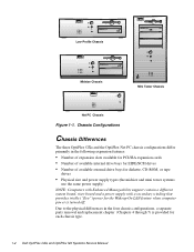
...) NOTE: Computers with Enhanced Manageability support contain a different system board, riser board and a power supply with a secondary winding that provides trickle ("flea") power for the Wakeup On LAN feature when computer power is provided for each chassis type. 1-2 Dell OptiPlex GXa and OptiPlex NX Systems Service Manual Low-Profile Chassis Midsize Chassis Mini Tower Chassis Net PC...
...) NOTE: Computers with Enhanced Manageability support contain a different system board, riser board and a power supply with a secondary winding that provides trickle ("flea") power for the Wakeup On LAN feature when computer power is provided for each chassis type. 1-2 Dell OptiPlex GXa and OptiPlex NX Systems Service Manual Low-Profile Chassis Midsize Chassis Mini Tower Chassis Net PC...
Service Manual
Page 19
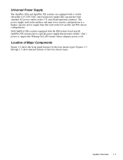
... the Wakeup On LAN feature when computer power is a higher-capacity power supply than that can operate from standard AC power outlets in the low-profile and NX chassis configurations. Universal Power Supply The OptiPlex GXa and OptiPlex NX systems are equipped with the EM system board and all international countries. Dell OptiPlex GXa systems equipped with a switchselectable (115-/230...
... the Wakeup On LAN feature when computer power is a higher-capacity power supply than that can operate from standard AC power outlets in the low-profile and NX chassis configurations. Universal Power Supply The OptiPlex GXa and OptiPlex NX systems are equipped with the EM system board and all international countries. Dell OptiPlex GXa systems equipped with a switchselectable (115-/230...
Service Manual
Page 20
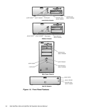
Front-Panel Features power button power indicator hard-disk drive access indicator 1-8 Dell OptiPlex GXa and OptiPlex NX Systems Service Manual power button power indicator reset button Low-Profile Chassis hard-disk drive access indicator diskette-drive access indicator power button power indicator reset button Midsize Chassis hard-disk drive access indicator diskette-drive access indicator power button reset button power indicator hard-disk drive access indicator Mini Tower Chassis Net PC Chassis Figure 1-2.
Front-Panel Features power button power indicator hard-disk drive access indicator 1-8 Dell OptiPlex GXa and OptiPlex NX Systems Service Manual power button power indicator reset button Low-Profile Chassis hard-disk drive access indicator diskette-drive access indicator power button power indicator reset button Midsize Chassis hard-disk drive access indicator diskette-drive access indicator power button reset button power indicator hard-disk drive access indicator Mini Tower Chassis Net PC Chassis Figure 1-2.

Service Manual
Page 23
..., which can support a mixture of avoiding resource conflicts. Internal View of the Net PC Chassis expansion-card cage expansion-card slot AC power receptacle Advanced Expansion Features The OptiPlex GXa systems contain advanced expansion subsystems that can be accessed by double-clicking the System icon in the Reference and Installation Guide describes...
..., which can support a mixture of avoiding resource conflicts. Internal View of the Net PC Chassis expansion-card cage expansion-card slot AC power receptacle Advanced Expansion Features The OptiPlex GXa systems contain advanced expansion subsystems that can be accessed by double-clicking the System icon in the Reference and Installation Guide describes...

Service Manual
Page 24
... HDLED connector ISA2 connector ISA1 connector PCI2 connector PCI1 connector Figure 1-8. power LED Wakeup On LAN power connector PCI1 connector Figure 1-7. The low-profile computers have three expansion-...during system start-up when DC power is receiving power; Riser Board for Net PC Computer Low-Profile Computer's Expansion-Card Slots The OptiPlex GXa low-profile computers have a...memory space, IRQ lines, and DMA channels to the riser board. OptiPlex NX Computer's Expansion-Card Slot The OptiPlex NX computer has one ISA expansion-card connector share a single expansion-card...
... HDLED connector ISA2 connector ISA1 connector PCI2 connector PCI1 connector Figure 1-8. power LED Wakeup On LAN power connector PCI1 connector Figure 1-7. The low-profile computers have three expansion-...during system start-up when DC power is receiving power; Riser Board for Net PC Computer Low-Profile Computer's Expansion-Card Slots The OptiPlex GXa low-profile computers have a...memory space, IRQ lines, and DMA channels to the riser board. OptiPlex NX Computer's Expansion-Card Slot The OptiPlex NX computer has one ISA expansion-card connector share a single expansion-card...

Service Manual
Page 26
... ISA2 connector ISA1 connector PCI3 connector P1 PCI2 connector PCI1 connector Figure 1-12. if off, the riser is receiving power; The riser board is active, incorporating PCI-to the riser cable) and an LED (see Figure 1-13). Riser... of seven expansion-card slots (see Figure 1-12). If the LED is on, the riser is not receiving power. The riser board has four ISA expansion-card connectors and five PCI expansion-card connectors. Two PCI expansion-card ...1-11. EM Riser Board for connecting the NIC to -PCI bridging. 1-14 Dell OptiPlex GXa and OptiPlex NX Systems Service Manual
... ISA2 connector ISA1 connector PCI3 connector P1 PCI2 connector PCI1 connector Figure 1-12. if off, the riser is receiving power; The riser board is active, incorporating PCI-to the riser cable) and an LED (see Figure 1-13). Riser... of seven expansion-card slots (see Figure 1-12). If the LED is on, the riser is not receiving power. The riser board has four ISA expansion-card connectors and five PCI expansion-card connectors. Two PCI expansion-card ...1-11. EM Riser Board for connecting the NIC to -PCI bridging. 1-14 Dell OptiPlex GXa and OptiPlex NX Systems Service Manual

Service Manual
Page 28
...-MB DIMMs up to all chassis configurations. Remote Management Support Features (Optional) For OptiPlex GXa and OptiPlex NX systems equipped with the enhanced manageability system board and power supply and an optional Wakeup On LAN-capable network card, the following subsections, and...upgrades are summarized in the following tasks may be performed by a system administrator at a remote location. 1-16 Dell OptiPlex GXa and OptiPlex NX Systems Service Manual Computer Service Information The following subsections provide service-related information about the computer. Main Memory Expansion ...
...-MB DIMMs up to all chassis configurations. Remote Management Support Features (Optional) For OptiPlex GXa and OptiPlex NX systems equipped with the enhanced manageability system board and power supply and an optional Wakeup On LAN-capable network card, the following subsections, and...upgrades are summarized in the following tasks may be performed by a system administrator at a remote location. 1-16 Dell OptiPlex GXa and OptiPlex NX Systems Service Manual Computer Service Information The following subsections provide service-related information about the computer. Main Memory Expansion ...

Service Manual
Page 36
Table 1-4. sometimes called "standby power." 1-24 Dell OptiPlex GXa and OptiPlex NX Systems Service Manual OptiPlex GXa DC Voltage Ranges Voltage Range Maximum Output Current +3.3 VDC +3.15 to +3.45 VDC 12.0 A1 (low-profile computers); 14.0 A1 (midsize and mini tower ...-profile computers or 140 W on the midsize/mini tower computers. 2 Withstands surges of up to 11.0 A to support disk start-up operations. 3 VFP (volts flea power) -
Table 1-4. sometimes called "standby power." 1-24 Dell OptiPlex GXa and OptiPlex NX Systems Service Manual OptiPlex GXa DC Voltage Ranges Voltage Range Maximum Output Current +3.3 VDC +3.15 to +3.45 VDC 12.0 A1 (low-profile computers); 14.0 A1 (midsize and mini tower ...-profile computers or 140 W on the midsize/mini tower computers. 2 Withstands surges of up to 11.0 A to support disk start-up operations. 3 VFP (volts flea power) -

Service Manual
Page 37
... and Mini Tower Chassis); PSON# should measure between +4 and +5 VDC except when the power button on and operating to control the power-supply fan speed. 3 Pin 5 - P3, P4, P5, P6, and P9 (All OptiPlex GXa Chassis) System Overview 1-25 Figures 1-18 through 1-20 show the wire side of ...the connectors without disconnecting them. Figure 1-18. Thermal fan-speed control (TFSC) is pressed, taking PSON# to its active-low state. 2 Pin 19 - DC Power Connector P1 1234 P2, P3...
... and Mini Tower Chassis); PSON# should measure between +4 and +5 VDC except when the power button on and operating to control the power-supply fan speed. 3 Pin 5 - P3, P4, P5, P6, and P9 (All OptiPlex GXa Chassis) System Overview 1-25 Figures 1-18 through 1-20 show the wire side of ...the connectors without disconnecting them. Figure 1-18. Thermal fan-speed control (TFSC) is pressed, taking PSON# to its active-low state. 2 Pin 19 - DC Power Connector P1 1234 P2, P3...
Service Manual
Page 38
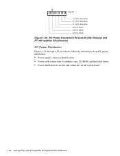
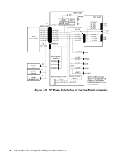
...) and P7 (All OptiPlex GXa Chassis) DC Power Distribution Figures 1-21 through 1-25 provide the following information about DC power distribution: • Power-supply connector identification • Power cable connections for diskette, tape, CD-ROM, and hard-disk drives • Power distribution to sockets and connectors on the system board 1-26 Dell OptiPlex GXa and OptiPlex NX Systems Service Manual
...) and P7 (All OptiPlex GXa Chassis) DC Power Distribution Figures 1-21 through 1-25 provide the following information about DC power distribution: • Power-supply connector identification • Power cable connections for diskette, tape, CD-ROM, and hard-disk drives • Power distribution to sockets and connectors on the system board 1-26 Dell OptiPlex GXa and OptiPlex NX Systems Service Manual
Service Manual
Page 40
Figure 1-22. system board +3 VDC battery P1 PWRGOOD POWER1 power RTC/ management NVRAM and NIC logic system power supply PSON# +5 VFP +5 VDC -5 VDC +12 VDC -12 VDC PSON# +5 VFP +5 VDC -5 VDC +12 VDC -12 VDC RISER +5 VDC -5 VDC +12 VDC -12 VDC P2 +3.3 ... MOUSE NOTE: On EM systems, +5VFP is routed to the integrated NIC logic on the system board and to P1 on the riser board. DC Power Distribution for the Low-Profile Computer 1-28 Dell OptiPlex GXa and OptiPlex NX Systems Service Manual
Figure 1-22. system board +3 VDC battery P1 PWRGOOD POWER1 power RTC/ management NVRAM and NIC logic system power supply PSON# +5 VFP +5 VDC -5 VDC +12 VDC -12 VDC PSON# +5 VFP +5 VDC -5 VDC +12 VDC -12 VDC RISER +5 VDC -5 VDC +12 VDC -12 VDC P2 +3.3 ... MOUSE NOTE: On EM systems, +5VFP is routed to the integrated NIC logic on the system board and to P1 on the riser board. DC Power Distribution for the Low-Profile Computer 1-28 Dell OptiPlex GXa and OptiPlex NX Systems Service Manual

Service Manual
Page 42
... for the Midsize Computer 1-30 Dell OptiPlex GXa and OptiPlex NX Systems Service Manual keyboard controller P1 PWRGOOD computer power supply PSON# +5 VFP +5 VDC -5 VDC +12 VDC -12 VDC P7 +3.3 VDC +3 VDC system board battery power management and NIC logic POWER1 RTC/ NVRAM PSON# +5 VFP +5 VDC -5 VDC +12 VDC -12 VDC POWER2 +5 VDC -5 VDC +12 VDC...
... for the Midsize Computer 1-30 Dell OptiPlex GXa and OptiPlex NX Systems Service Manual keyboard controller P1 PWRGOOD computer power supply PSON# +5 VFP +5 VDC -5 VDC +12 VDC -12 VDC P7 +3.3 VDC +3 VDC system board battery power management and NIC logic POWER1 RTC/ NVRAM PSON# +5 VFP +5 VDC -5 VDC +12 VDC -12 VDC POWER2 +5 VDC -5 VDC +12 VDC...

Service Manual
Page 44
... its loaded condition. Table 1-5. OptiPlex NX Computer Power Supply The OptiPlex NX computers have an 80-W computer power supply. The computer power supply provides the DC operating voltages and currents listed in Table 1-5. The power supply can operate from an AC power source of up operations. 3 VFP (volts flea power) - sometimes called "standby power." 1-32 Dell OptiPlex GXa and OptiPlex NX Systems Service Manual Therefore...
... its loaded condition. Table 1-5. OptiPlex NX Computer Power Supply The OptiPlex NX computers have an 80-W computer power supply. The computer power supply provides the DC operating voltages and currents listed in Table 1-5. The power supply can operate from an AC power source of up operations. 3 VFP (volts flea power) - sometimes called "standby power." 1-32 Dell OptiPlex GXa and OptiPlex NX Systems Service Manual Therefore...

Service Manual
Page 45
...) 1 Pin 11 - PWRGOOD should measure between +4 and +5 VDC when the power supply is on the front panel is a power-supply input signal used to control the power-supply fan speed. 3 Pin 5 - Figure 1-26. DC Power Connector P2 for the OptiPlex NX P2 1 2 34 5 6 +3.3 VDC (blue/white) +3.3 VDC (blue...pressed, taking PSON# to indicate that all power-supply output voltages are within the ranges specified in Table 1-5. DC Power Connector P1 for the OptiPlex NX System Overview 1-33 OptiPlex NX Pin Assignments for the DC Power Connectors The power-supply output voltages can be measured at ...
...) 1 Pin 11 - PWRGOOD should measure between +4 and +5 VDC when the power supply is on the front panel is a power-supply input signal used to control the power-supply fan speed. 3 Pin 5 - Figure 1-26. DC Power Connector P2 for the OptiPlex NX P2 1 2 34 5 6 +3.3 VDC (blue/white) +3.3 VDC (blue...pressed, taking PSON# to indicate that all power-supply output voltages are within the ranges specified in Table 1-5. DC Power Connector P1 for the OptiPlex NX System Overview 1-33 OptiPlex NX Pin Assignments for the DC Power Connectors The power-supply output voltages can be measured at ...
Service Manual
Page 46
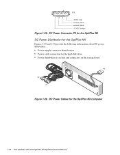
DC Power Connector P3 for the OptiPlex NX DC Power Distribution for the OptiPlex NX Figures 1-29 and 1-30 provide the following information about DC power distribution: • Power-supply connector identification • Power cable connection for the OptiPlex NX Computer 1-34 Dell OptiPlex GXa and OptiPlex NX Systems Service Manual DC Power Cables for the hard-disk drive • Power distribution to sockets and connectors on the system board P3 P2 P1 Figure 1-29. P3 1234 +5 VDC (red) common (black) common (black) +12 VDC (yellow) Figure 1-28.
DC Power Connector P3 for the OptiPlex NX DC Power Distribution for the OptiPlex NX Figures 1-29 and 1-30 provide the following information about DC power distribution: • Power-supply connector identification • Power cable connection for the OptiPlex NX Computer 1-34 Dell OptiPlex GXa and OptiPlex NX Systems Service Manual DC Power Cables for the hard-disk drive • Power distribution to sockets and connectors on the system board P3 P2 P1 Figure 1-29. P3 1234 +5 VDC (red) common (black) common (black) +12 VDC (yellow) Figure 1-28.


