Service Manual
Page 4
... 1-21 Hard-Disk Drive Service Information 1-22 Hard-Disk Drive for the Net PC Computer 1-22 Hard-Disk Drive for the Low-Profile Computer 1-23 Hard-Disk Drive for the Midsize Computer 1-23 Hard-Disk Drive for the Mini Tower Computer 1-23 Power-Supply Service Data 1-23 Pin Assignments for the DC Power Connectors 1-25 DC Power Distribution 1-26 OptiPlex NX Computer...
... 1-21 Hard-Disk Drive Service Information 1-22 Hard-Disk Drive for the Net PC Computer 1-22 Hard-Disk Drive for the Low-Profile Computer 1-23 Hard-Disk Drive for the Midsize Computer 1-23 Hard-Disk Drive for the Mini Tower Computer 1-23 Power-Supply Service Data 1-23 Pin Assignments for the DC Power Connectors 1-25 DC Power Distribution 1-26 OptiPlex NX Computer...
Service Manual
Page 9
... 4-17 Figure 4-16. Floor Stand Removal 5-4 Figure 5-3. Control Panel Removal 5-8 Figure 5-7. Hard-Disk Drive Bracket Removal 5-12 Figure 5-12. DC Power Cables for the OptiPlex NX 1-33 Figure 1-28. Internal View of the Midsize Computer 5-3 Figure 5-2. System Power-Supply ... Connector P3 for the OptiPlex NX 1-33 Figure 1-27. DC Power Distribution for the OptiPlex NX Computer . . . . 1-35 Figure 2-1. Eject, Power, and Reset Button Removal 4-5 Figure 4-4. Front-Panel Insert Removal 4-6 Figure 4-5. Control Panel Removal 4-7 Figure 4-6. Hard-Disk Drive Assembly Removal 4-11 Figure...
... 4-17 Figure 4-16. Floor Stand Removal 5-4 Figure 5-3. Control Panel Removal 5-8 Figure 5-7. Hard-Disk Drive Bracket Removal 5-12 Figure 5-12. DC Power Cables for the OptiPlex NX 1-33 Figure 1-28. Internal View of the Midsize Computer 5-3 Figure 5-2. System Power-Supply ... Connector P3 for the OptiPlex NX 1-33 Figure 1-27. DC Power Distribution for the OptiPlex NX Computer . . . . 1-35 Figure 2-1. Eject, Power, and Reset Button Removal 4-5 Figure 4-4. Front-Panel Insert Removal 4-6 Figure 4-5. Control Panel Removal 4-7 Figure 4-6. Hard-Disk Drive Assembly Removal 4-11 Figure...

Service Manual
Page 11
...OptiPlex NX DC Voltage Ranges 1-32 Technical Specifications 1-36 POST Beep Codes 3-2 System Error Messages 3-4 System Setup Categories A-3 xiii Riser Board Removal 7-11 Figure 7-11. Table 1-2. Control Panel Removal 7-5 Figure 7-5. SEC Cartridge/Heat Sink Removal 7-14 Figure 7-15. Table 1-6. System Power-Supply Removal 7-7 Figure 7-7. System Setup Screens A-2 Tables Table 1-1. Table 3-1. Table 3-2. Table 1-4. Hard...-Disk Drive Removal 7-6 Figure 7-6. DIMM Installation 7-12 Figure 7-13. System...
...OptiPlex NX DC Voltage Ranges 1-32 Technical Specifications 1-36 POST Beep Codes 3-2 System Error Messages 3-4 System Setup Categories A-3 xiii Riser Board Removal 7-11 Figure 7-11. Table 1-2. Control Panel Removal 7-5 Figure 7-5. SEC Cartridge/Heat Sink Removal 7-14 Figure 7-15. Table 1-6. System Power-Supply Removal 7-7 Figure 7-7. System Setup Screens A-2 Tables Table 1-1. Table 3-1. Table 3-2. Table 1-4. Hard...-Disk Drive Removal 7-6 Figure 7-6. DIMM Installation 7-12 Figure 7-13. System...
Service Manual
Page 16
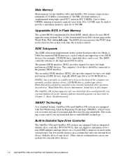
... be connected to the high-speed PCI local bus. This warning occurs only if you use hard-disk drives with Self-Monitoring Analysis Reporting Technology (SMART), which can accommodate two external drive devices. 1-4 Dell OptiPlex GXa and OptiPlex NX Systems Service Manual EIDE Subsystem The EIDE subsystem implemented on the system board provides two Mode-4, DMA bus...
... be connected to the high-speed PCI local bus. This warning occurs only if you use hard-disk drives with Self-Monitoring Analysis Reporting Technology (SMART), which can accommodate two external drive devices. 1-4 Dell OptiPlex GXa and OptiPlex NX Systems Service Manual EIDE Subsystem The EIDE subsystem implemented on the system board provides two Mode-4, DMA bus...
Service Manual
Page 20
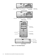
Front-Panel Features power button power indicator hard-disk drive access indicator 1-8 Dell OptiPlex GXa and OptiPlex NX Systems Service Manual power button power indicator reset button Low-Profile Chassis hard-disk drive access indicator diskette-drive access indicator power button power indicator reset button Midsize Chassis hard-disk drive access indicator diskette-drive access indicator power button reset button power indicator hard-disk drive access indicator Mini Tower Chassis Net PC Chassis Figure 1-2.
Front-Panel Features power button power indicator hard-disk drive access indicator 1-8 Dell OptiPlex GXa and OptiPlex NX Systems Service Manual power button power indicator reset button Low-Profile Chassis hard-disk drive access indicator diskette-drive access indicator power button power indicator reset button Midsize Chassis hard-disk drive access indicator diskette-drive access indicator power button reset button power indicator hard-disk drive access indicator Mini Tower Chassis Net PC Chassis Figure 1-2.

Service Manual
Page 23
... ring hard-disk drive security access lock security cable slot parallel port connector serial port 1 connector mouse connector keyboard connector USB connectors (2) serial port 2 connector video connector NIC connector (optional) Figure 1-6. Internal View of the Net PC Chassis expansion-card cage expansion-card slot AC power receptacle Advanced Expansion Features The OptiPlex GXa...
... ring hard-disk drive security access lock security cable slot parallel port connector serial port 1 connector mouse connector keyboard connector USB connectors (2) serial port 2 connector video connector NIC connector (optional) Figure 1-6. Internal View of the Net PC Chassis expansion-card cage expansion-card slot AC power receptacle Advanced Expansion Features The OptiPlex GXa...
Service Manual
Page 34
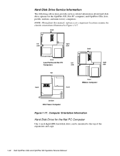
... manual, references to the top of the expansion-card cage. 1-22 Dell OptiPlex GXa and OptiPlex NX Systems Service Manual Hard-Disk Drive Service Information The following subsections provide service-related information about hard-disk drive options for the Net PC Computer One 1-inch-high EIDE hard-disk drive can be mounted to component locations assume the chassis orientations illustrated...
... manual, references to the top of the expansion-card cage. 1-22 Dell OptiPlex GXa and OptiPlex NX Systems Service Manual Hard-Disk Drive Service Information The following subsections provide service-related information about hard-disk drive options for the Net PC Computer One 1-inch-high EIDE hard-disk drive can be mounted to component locations assume the chassis orientations illustrated...
Service Manual
Page 38
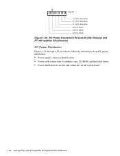
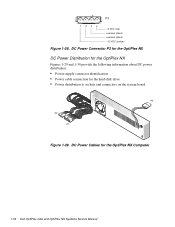
... (All OptiPlex GXa Chassis) DC Power Distribution Figures 1-21 through 1-25 provide the following information about DC power distribution: • Power-supply connector identification • Power cable connections for diskette, tape, CD-ROM, and hard-disk drives • Power distribution to sockets and connectors on the system board 1-26 Dell OptiPlex GXa and OptiPlex NX Systems Service...
... (All OptiPlex GXa Chassis) DC Power Distribution Figures 1-21 through 1-25 provide the following information about DC power distribution: • Power-supply connector identification • Power cable connections for diskette, tape, CD-ROM, and hard-disk drives • Power distribution to sockets and connectors on the system board 1-26 Dell OptiPlex GXa and OptiPlex NX Systems Service...
Service Manual
Page 40
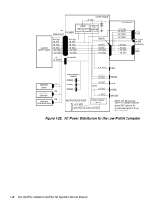
Figure 1-22. DC Power Distribution for the Low-Profile Computer 1-28 Dell OptiPlex GXa and OptiPlex NX Systems Service Manual system board +3 VDC battery P1 PWRGOOD POWER1 power RTC/ management NVRAM and NIC logic system power supply PSON# +5 VFP +5 VDC -5 VDC +12 ...+5 VDC +12 VDC -12 VDC +5 VDC -5 VDC +12 VDC -12 VDC PCI1 PCI2 P1 (only on EM systems) ISA1 ISA2 optional P3 drive P4 3.5-inch diskette P5 internal hard-disk drive +12 VDC FAN main memory sockets DIMM_A DIMM_B DIMM_C +5 VFP +5 VDC +5 VDC fuses +5 VDC PANEL USB KYBD +5 VDC MICROPROCESSOR +3.3 VDC processor core...
Figure 1-22. DC Power Distribution for the Low-Profile Computer 1-28 Dell OptiPlex GXa and OptiPlex NX Systems Service Manual system board +3 VDC battery P1 PWRGOOD POWER1 power RTC/ management NVRAM and NIC logic system power supply PSON# +5 VFP +5 VDC -5 VDC +12 ...+5 VDC +12 VDC -12 VDC +5 VDC -5 VDC +12 VDC -12 VDC PCI1 PCI2 P1 (only on EM systems) ISA1 ISA2 optional P3 drive P4 3.5-inch diskette P5 internal hard-disk drive +12 VDC FAN main memory sockets DIMM_A DIMM_B DIMM_C +5 VFP +5 VDC +5 VDC fuses +5 VDC PANEL USB KYBD +5 VDC MICROPROCESSOR +3.3 VDC processor core...

Service Manual
Page 42
... +12 VDC -12 VDC PCI1 through PCI3 P1 (on EM systems only) ISA1 through ISA3 +12 VDC FAN internal P2 hard-disk drive internal P3 hard-disk drive P4 3.5-inch diskette drive P5* optional drive P6* optional drive main memory sockets DIMM_A DIMM_B DIMM_C +5 VFP +5 VDC PANEL +5 VDC +5 VDC USB KYBD fuses (2) +5 VDC MICROPROCESSOR processor core regulator... board. * Some computers have an additional connector (P9) that may be used instead of P5 or P6. DC Power Distribution for the Midsize Computer 1-30 Dell OptiPlex GXa and OptiPlex NX Systems Service Manual
... +12 VDC -12 VDC PCI1 through PCI3 P1 (on EM systems only) ISA1 through ISA3 +12 VDC FAN internal P2 hard-disk drive internal P3 hard-disk drive P4 3.5-inch diskette drive P5* optional drive P6* optional drive main memory sockets DIMM_A DIMM_B DIMM_C +5 VFP +5 VDC PANEL +5 VDC +5 VDC USB KYBD fuses (2) +5 VDC MICROPROCESSOR processor core regulator... board. * Some computers have an additional connector (P9) that may be used instead of P5 or P6. DC Power Distribution for the Midsize Computer 1-30 Dell OptiPlex GXa and OptiPlex NX Systems Service Manual

Service Manual
Page 44
...when you measure these voltages, the DC power connectors must be connected to support disk start-up operations. 3 VFP (volts flea power) - OptiPlex NX DC Voltage Ranges Voltage Range Maximum Output Current1 +3.3 VDC +3.14 to +3.47 VDC 6.0 A1 +5 VDC +4.75 to +5.25 VDC 12.0... VDC 1.2 A 1 The combined load on the system board and hard-disk drive. . The computer power supply provides the DC operating voltages and currents listed in Table 1-5. sometimes called "standby power." 1-32 Dell OptiPlex GXa and OptiPlex NX Systems Service Manual The power supply can operate from an AC power ...
...when you measure these voltages, the DC power connectors must be connected to support disk start-up operations. 3 VFP (volts flea power) - OptiPlex NX DC Voltage Ranges Voltage Range Maximum Output Current1 +3.3 VDC +3.14 to +3.47 VDC 6.0 A1 +5 VDC +4.75 to +5.25 VDC 12.0... VDC 1.2 A 1 The combined load on the system board and hard-disk drive. . The computer power supply provides the DC operating voltages and currents listed in Table 1-5. sometimes called "standby power." 1-32 Dell OptiPlex GXa and OptiPlex NX Systems Service Manual The power supply can operate from an AC power ...
Service Manual
Page 46
DC Power Cables for the hard-disk drive • Power distribution to sockets and connectors on the system board P3 P2 P1 Figure 1-29. DC Power Connector P3 for the OptiPlex NX DC Power Distribution for the OptiPlex NX Figures 1-29 and 1-30 provide the following information about DC power distribution: • Power-supply connector identification • Power cable connection for the OptiPlex NX Computer 1-34 Dell OptiPlex GXa and OptiPlex NX Systems Service Manual P3 1234 +5 VDC (red) common (black) common (black) +12 VDC (yellow) Figure 1-28.
DC Power Cables for the hard-disk drive • Power distribution to sockets and connectors on the system board P3 P2 P1 Figure 1-29. DC Power Connector P3 for the OptiPlex NX DC Power Distribution for the OptiPlex NX Figures 1-29 and 1-30 provide the following information about DC power distribution: • Power-supply connector identification • Power cable connection for the OptiPlex NX Computer 1-34 Dell OptiPlex GXa and OptiPlex NX Systems Service Manual P3 1234 +5 VDC (red) common (black) common (black) +12 VDC (yellow) Figure 1-28.
Service Manual
Page 47
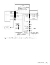
... VDC -12 VDC P2 POWER_2 +3.3 VDC +3.3 VDC +5 VDC +12 VDC -12 VDC RISER +3.3 VDC +5 VDC +12 VDC -12 VDC riser board P1 PCI1 internal P3 hard-disk drive +12 VDC FAN main memory sockets DIMM_A DIMM_B DIMM_C +5 VFP +5 VDC PANEL +5 VDC USB +5 VDC KYBD fuses (2) +5 VDC MICROPROCESSOR processor core regulator +3.3 VDC core... NOTE: +5VFP is routed to the integrated NIC logic on the system board and to P1 on the riser board. DC Power Distribution for the OptiPlex NX Computer System Overview 1-35 Figure 1-30.
... VDC -12 VDC P2 POWER_2 +3.3 VDC +3.3 VDC +5 VDC +12 VDC -12 VDC RISER +3.3 VDC +5 VDC +12 VDC -12 VDC riser board P1 PCI1 internal P3 hard-disk drive +12 VDC FAN main memory sockets DIMM_A DIMM_B DIMM_C +5 VFP +5 VDC PANEL +5 VDC USB +5 VDC KYBD fuses (2) +5 VDC MICROPROCESSOR processor core regulator +3.3 VDC core... NOTE: +5VFP is routed to the integrated NIC logic on the system board and to P1 on the riser board. DC Power Distribution for the OptiPlex NX Computer System Overview 1-35 Figure 1-30.
Service Manual
Page 50
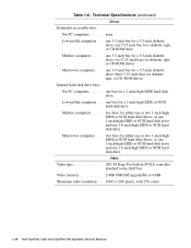
...hard-disk drive and one 1.6-inch-high EIDE or SCSI harddisk drive Video Video type ATI 3D Rage Pro built-in SVGA controller attached to the AGP bus Video memory 2-MB SGRAM, upgradable to 4 MB Maximum video resolution . . . 1600 x 1200 pixels, with 256 colors 1-38 Dell OptiPlex GXa and OptiPlex NX... Systems Service Manual two bays for a diskette, tape, or CD-ROM drive Midsize computers . . . . . Table 1-6. Technical Specifications (continued) Drives Externally accessible bays: Net PC computers none Low-...
...hard-disk drive and one 1.6-inch-high EIDE or SCSI harddisk drive Video Video type ATI 3D Rage Pro built-in SVGA controller attached to the AGP bus Video memory 2-MB SGRAM, upgradable to 4 MB Maximum video resolution . . . 1600 x 1200 pixels, with 256 colors 1-38 Dell OptiPlex GXa and OptiPlex NX... Systems Service Manual two bays for a diskette, tape, or CD-ROM drive Midsize computers . . . . . Table 1-6. Technical Specifications (continued) Drives Externally accessible bays: Net PC computers none Low-...
Service Manual
Page 51
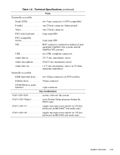
...PCI local bus Diskette drive 34-pin connector CD-ROM drive audio interface 4-pin connector Key Combinations two 40-pin connectors on enhanced manageability OptiPlex Gxa systems and all OptiPlex NX systems) USB two ...USB-compliant connectors Audio line-in 2.0-V rms (maximum); Table 1-6. stereo Audio microphone . . . . . 89-mV rms (maximum); stereo (at 32 ohms minimum impedance) Internally accessible: EIDE hard-disk drive...
...PCI local bus Diskette drive 34-pin connector CD-ROM drive audio interface 4-pin connector Key Combinations two 40-pin connectors on enhanced manageability OptiPlex Gxa systems and all OptiPlex NX systems) USB two ...USB-compliant connectors Audio line-in 2.0-V rms (maximum); Table 1-6. stereo Audio microphone . . . . . 89-mV rms (maximum); stereo (at 32 ohms minimum impedance) Internally accessible: EIDE hard-disk drive...
Service Manual
Page 52
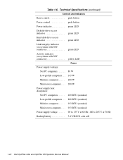
Table 1-6. Technical Specifications (continued) Controls and Indicators Reset control push button Power control push button Power indicator green LED Diskette-drive access indicator green LED Hard-disk drive access indicator green LED Link integrity indicator (on systems with NIC connector green LED Activity indicator (on systems with NIC connector yellow LED Power Power ... computers. . . . 913 BTU (nominal) Power supply voltage 90 to 135 V at 60 Hz; 180 to 265 V at 50 Hz Backup battery 3-V CR2032 coin cell 1-40 Dell OptiPlex GXa and OptiPlex NX Systems Service Manual
Table 1-6. Technical Specifications (continued) Controls and Indicators Reset control push button Power control push button Power indicator green LED Diskette-drive access indicator green LED Hard-disk drive access indicator green LED Link integrity indicator (on systems with NIC connector green LED Activity indicator (on systems with NIC connector yellow LED Power Power ... computers. . . . 913 BTU (nominal) Power supply voltage 90 to 135 V at 60 Hz; 180 to 265 V at 50 Hz Backup battery 3-V CR2032 coin cell 1-40 Dell OptiPlex GXa and OptiPlex NX Systems Service Manual

Service Manual
Page 55
...Beep Codes and Error Messages," also contains information to the appropriate user documentation for information about backing up any data on the hard-disk drive if the system's condition permits. In particular, was performing at the end of a problem or indicate the appropriate troubleshooting procedure...she is also provided at the time the problem occurred. Proceed to step 3. Is the problem a result of the Dell OptiPlex GXa and OptiPlex NX families. Proceed to describe the problem and the conditions under which it occurs. Basic Troubleshooting 2-1 Can the user duplicate the...
...Beep Codes and Error Messages," also contains information to the appropriate user documentation for information about backing up any data on the hard-disk drive if the system's condition permits. In particular, was performing at the end of a problem or indicate the appropriate troubleshooting procedure...she is also provided at the time the problem occurred. Proceed to step 3. Is the problem a result of the Dell OptiPlex GXa and OptiPlex NX families. Proceed to describe the problem and the conditions under which it occurs. Basic Troubleshooting 2-1 Can the user duplicate the...
Service Manual
Page 58
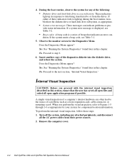
... to Figures 1-3 through 1-6 as appropriate for your system for component location information. Remove the computer cover. 2-4 Dell OptiPlex GXa and OptiPlex NX Systems Service Manual vide status information. Proceed to the source of a computer's interior hardware can indicate problems or ... codes: A beep code is a series of the following: • Diskette-drive and hard-disk drive access indicators: These indicators light up during the boot routine, troubleshoot the diskette drive or hard-disk drive subsystem, as a loose expansion card, cable connector, or mounting screw. Does the...
... to Figures 1-3 through 1-6 as appropriate for your system for component location information. Remove the computer cover. 2-4 Dell OptiPlex GXa and OptiPlex NX Systems Service Manual vide status information. Proceed to the source of a computer's interior hardware can indicate problems or ... codes: A beep code is a series of the following: • Diskette-drive and hard-disk drive access indicators: These indicators light up during the boot routine, troubleshoot the diskette drive or hard-disk drive subsystem, as a loose expansion card, cable connector, or mounting screw. Does the...
Service Manual
Page 60
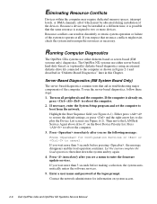
...message: Press for information on the Boot Device Priority list. The OptiPlex NX systems use either server-based, hard-disk-based, or (optionally) diskette-based diagnostics using an external diskette-drive kit connected to the computer as necessary. Turn on , press ...computer. To run the server-based diagnostics, follow these steps: 1. Then move the LANDesk Service Agent above drive C: on system access. 2-6 Dell OptiPlex GXa and OptiPlex NX Systems Service Manual Press immediately after you wait more than 5 seconds before making a selection, the system ...
...message: Press for information on the Boot Device Priority list. The OptiPlex NX systems use either server-based, hard-disk-based, or (optionally) diskette-based diagnostics using an external diskette-drive kit connected to the computer as necessary. Turn on , press ...computer. To run the server-based diagnostics, follow these steps: 1. Then move the LANDesk Service Agent above drive C: on system access. 2-6 Dell OptiPlex GXa and OptiPlex NX Systems Service Manual Press immediately after you wait more than 5 seconds before making a selection, the system ...
Service Manual
Page 62
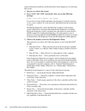
... the monitor screen for Setup. Verify the correct operation of main memory (RAM) required for a thorough test of the hard-disk drive 2-8 Dell OptiPlex GXa and OptiPlex NX Systems Service Manual Otherwise, see the following test groups: • RAM Tests - board controller chip • Mouse Test...message indicating that the diagnostics is needed to isolate a failure • Run All Tests - Runs selected tests from the hard-disk drive. The diskette-based diagnostics consists of the video controller and the video control circuitry • Keyboard Tests - Check all ...
... the monitor screen for Setup. Verify the correct operation of main memory (RAM) required for a thorough test of the hard-disk drive 2-8 Dell OptiPlex GXa and OptiPlex NX Systems Service Manual Otherwise, see the following test groups: • RAM Tests - board controller chip • Mouse Test...message indicating that the diagnostics is needed to isolate a failure • Run All Tests - Runs selected tests from the hard-disk drive. The diskette-based diagnostics consists of the video controller and the video control circuitry • Keyboard Tests - Check all ...


