Service Manual
Page 10
.... • Integrated Universal Serial Bus (USB) controller with the Intel 82440FX PCIset. • SMART support-compliant hard-disk drives and SMART support in the system BIOS, which warns you at system start-up if a hard-disk drive has become unreliable. • Quick tests feature in the diskette-based diagnostics (for more information about Run Quick Tests, see "Technical Specifications" found in a traditional personal computer, the Dell OptiPlex GXpro desktop systems include the following...
.... • Integrated Universal Serial Bus (USB) controller with the Intel 82440FX PCIset. • SMART support-compliant hard-disk drives and SMART support in the system BIOS, which warns you at system start-up if a hard-disk drive has become unreliable. • Quick tests feature in the diskette-based diagnostics (for more information about Run Quick Tests, see "Technical Specifications" found in a traditional personal computer, the Dell OptiPlex GXpro desktop systems include the following...
Service Manual
Page 12
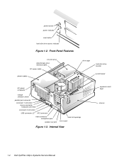
power button power indicator reset button hard-disk drive access indicator Figure 1-2. Internal View expansion-card cage chassis 1-4 Dell OptiPlex GXpro Systems Service Manual Front-Panel Features 3.5-inch drive diskette/tape drive interface cable DC power cable power supply drive cage hard-disk drive bracket system board AC power receptacle voltage selection switch parallel port connector serial port 1 connector mouse connector keyboard connector serial port 2 connector USB connector (2) NIC connector video connector microphone jack speaker-out jack card-slot openings line-in jack...
power button power indicator reset button hard-disk drive access indicator Figure 1-2. Internal View expansion-card cage chassis 1-4 Dell OptiPlex GXpro Systems Service Manual Front-Panel Features 3.5-inch drive diskette/tape drive interface cable DC power cable power supply drive cage hard-disk drive bracket system board AC power receptacle voltage selection switch parallel port connector serial port 1 connector mouse connector keyboard connector serial port 2 connector USB connector (2) NIC connector video connector microphone jack speaker-out jack card-slot openings line-in jack...
Service Manual
Page 14
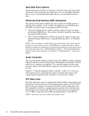
... to external audio devices (speakers, microphone). NOTE: Some users may use an ISA video adapter card. 1-6 Dell OptiPlex GXpro Systems Service Manual performance EIDE devices. For detailed information about the data storage subsystem, see Chapter 9, "Installing Drives," in the User's Guide provides instructions for connecting the system unit to two high- Audio Controller The system board has a built-in one -inch-high, hard-disk drive. Chapter 6, "Using the Integrated Audio Controller," in the User's Guide. Enhanced Dual-Interface EIDE Subsystem The enhanced dual-interface...
... to external audio devices (speakers, microphone). NOTE: Some users may use an ISA video adapter card. 1-6 Dell OptiPlex GXpro Systems Service Manual performance EIDE devices. For detailed information about the data storage subsystem, see Chapter 9, "Installing Drives," in the User's Guide provides instructions for connecting the system unit to two high- Audio Controller The system board has a built-in one -inch-high, hard-disk drive. Chapter 6, "Using the Integrated Audio Controller," in the User's Guide. Enhanced Dual-Interface EIDE Subsystem The enhanced dual-interface...
Service Manual
Page 15
..., and computer speakers. Desktop Chassis The system unit can also be set horizontally or vertically, when used . The floor stand attaches to alert the user that monitors the processor's temperature. Chapter 5, "Using the Network Interface Controller," in the User's Guide provides instructions for connecting the system to, and configuring it for multiple USB-compliant devices. If the critical threshold is running. NIC GXpro systems contain either a category-3 or a category-5 ethernet cable.
..., and computer speakers. Desktop Chassis The system unit can also be set horizontally or vertically, when used . The floor stand attaches to alert the user that monitors the processor's temperature. Chapter 5, "Using the Network Interface Controller," in the User's Guide provides instructions for connecting the system to, and configuring it for multiple USB-compliant devices. If the critical threshold is running. NIC GXpro systems contain either a category-3 or a category-5 ethernet cable.
Service Manual
Page 20
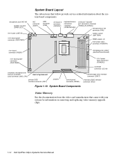
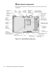
...speaker-out jack (SPKR-OUT) line-in jack (LINE-IN) riser board power connector (RSR PWR1) System Board Layout The subsections that came with your system for information on removing and replacing video-memory upgrade chips. 1-12 Dell OptiPlex GXpro Systems Service Manual NIC connector (ENET) USB connector (USB) serial port 2 connector (SERIAL2) keyboard/mouse connectors (stacked) (KYBD/MOUSE) serial port 1/parallel port connectors (stacked) (PARALLEL/SERIAL) microprocessor fan connector (FAN) battery socket (BATTERY) DIMM sockets (4) main power input connector (POWER1) riser board...
...speaker-out jack (SPKR-OUT) line-in jack (LINE-IN) riser board power connector (RSR PWR1) System Board Layout The subsections that came with your system for information on removing and replacing video-memory upgrade chips. 1-12 Dell OptiPlex GXpro Systems Service Manual NIC connector (ENET) USB connector (USB) serial port 2 connector (SERIAL2) keyboard/mouse connectors (stacked) (KYBD/MOUSE) serial port 1/parallel port connectors (stacked) (PARALLEL/SERIAL) microprocessor fan connector (FAN) battery socket (BATTERY) DIMM sockets (4) main power input connector (POWER1) riser board...
Service Manual
Page 22
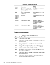
... else not installed Installed if the microprocessor's internal speed is used by keyboard controller to enable IRQ8 through IRQ15. Not installed (reserved, do not change ) Microprocessor speed. IRQ1 Generated by secondary parallel port. IRQ2 Generated internally by super I /O controller to indicate that device connected to parallel port requires service. 1-14 Dell OptiPlex GXpro Systems Service Manual IRQ6 Generated by interrupt controller to indicate that diskette or tape drive requires service. Used for COM1 or COM3). Jumper PSWD BIOS RSRVD4...
... else not installed Installed if the microprocessor's internal speed is used by keyboard controller to enable IRQ8 through IRQ15. Not installed (reserved, do not change ) Microprocessor speed. IRQ1 Generated by secondary parallel port. IRQ2 Generated internally by super I /O controller to indicate that device connected to parallel port requires service. 1-14 Dell OptiPlex GXpro Systems Service Manual IRQ6 Generated by interrupt controller to indicate that diskette or tape drive requires service. Used for COM1 or COM3). Jumper PSWD BIOS RSRVD4...
Service Manual
Page 25
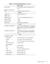
... BIOS address F000:0000h-F0000:FFFFh Drives Externally accessible bays . . . one 1.6-inch-high and one 1-inch-high EIDE or SCSI hard-disk drive Ports Externally accessible: Serial (DTE two 9-pin connectors; 16550-compatible Parallel one 25-hole connector (bidirectional) Video one 3.5-inch bay, dedicated to a 3.5-inch diskette drive; two hard-disk drive bays; one 15-hole connector (on add-in video card) PS/2-style keyboard . . . . . 6-pin mini-DIN PS/2-compatible mouse 6-pin mini-DIN NIC RJ45 connector USB two USB...
... BIOS address F000:0000h-F0000:FFFFh Drives Externally accessible bays . . . one 1.6-inch-high and one 1-inch-high EIDE or SCSI hard-disk drive Ports Externally accessible: Serial (DTE two 9-pin connectors; 16550-compatible Parallel one 25-hole connector (bidirectional) Video one 3.5-inch bay, dedicated to a 3.5-inch diskette drive; two hard-disk drive bays; one 15-hole connector (on add-in video card) PS/2-style keyboard . . . . . 6-pin mini-DIN PS/2-compatible mouse 6-pin mini-DIN NIC RJ45 connector USB two USB...
Service Manual
Page 26
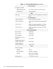
Technical Specifications (continued) Ports (continued) Internally accessible: EIDE hard-disk drive . . . . Table 1-5. two 40-pin connectors on PCI local bus Diskette drive 34-pin connector Video Video type PCI video card (see manufacturer's specifications) Key Combinations
Technical Specifications (continued) Ports (continued) Internally accessible: EIDE hard-disk drive . . . . Table 1-5. two 40-pin connectors on PCI local bus Diskette drive 34-pin connector Video Video type PCI video card (see manufacturer's specifications) Key Combinations
Service Manual
Page 29
.... No. After the user describes the problem, follow these steps: 1. Can the user duplicate the problem? Chapter 2 Basic Troubleshooting This chapter describes basic troubleshooting procedures that you first contact a user who has a problem, ask the user to load and start the diskette-based diagnostics is making an error, such as typing an incorrect key combination or entering a command incorrectly. Yes. Ask the user to try to back...
.... No. After the user describes the problem, follow these steps: 1. Can the user duplicate the problem? Chapter 2 Basic Troubleshooting This chapter describes basic troubleshooting procedures that you first contact a user who has a problem, ask the user to load and start the diskette-based diagnostics is making an error, such as typing an incorrect key combination or entering a command incorrectly. Yes. Ask the user to try to back...
Service Manual
Page 30
... video monitor, see the documentation for the monitor. 7. Verify that no keys are properly connected to replace the keyboard. 2-2 Dell OptiPlex GXpro Systems Service Manual If one of the serial port connectors, and its captive screws must be secure enough to the proper connectors on the back of the monitor. Inspect the keyboard to ensure that the keyboard and mouse interface cables are identical except for any devices connected to the serial ports, parallel port, and USB...
... video monitor, see the documentation for the monitor. 7. Verify that no keys are properly connected to replace the keyboard. 2-2 Dell OptiPlex GXpro Systems Service Manual If one of the serial port connectors, and its captive screws must be secure enough to the proper connectors on the back of the monitor. Inspect the keyboard to ensure that the keyboard and mouse interface cables are identical except for any devices connected to the serial ports, parallel port, and USB...
Service Manual
Page 32
... in their power sources. 2. To perform the internal visual inspection, follow these steps: 1. • System error messages: These messages can get extremely hot. Yes. A simple visual inspection of each chip. 2-4 Dell OptiPlex GXpro Systems Service Manual WARNING: The microprocessor can indicate problems or pro- No. Proceed to the source of the diagnostics diskette into the diskette drive, and reboot the system. Turn off...
... in their power sources. 2. To perform the internal visual inspection, follow these steps: 1. • System error messages: These messages can get extremely hot. Yes. A simple visual inspection of each chip. 2-4 Dell OptiPlex GXpro Systems Service Manual WARNING: The microprocessor can indicate problems or pro- No. Proceed to the source of the diagnostics diskette into the diskette drive, and reboot the system. Turn off...
Service Manual
Page 35
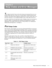
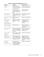
...of the problem, run the appropriate tests to indicate a failure, you identify a faulty component or assembly. POST Beep Codes Beep Code Error Probable Causes 1-3 Monitor not detected Disconnected or faulty monitor 1-1-3 NVRAM write/read failure Defective system board 1-1-4 BIOS checksum failure Faulty BIOS or defective system board 1-2-1 Programmable interval-timer Defective system board failure 1-2-2 DMA initialization failure 1-2-3 DMA page register write/ read failure Beep Codes and Error Messages 3-1 POST Beep Codes If the monitor cannot display error messages during...
...of the problem, run the appropriate tests to indicate a failure, you identify a faulty component or assembly. POST Beep Codes Beep Code Error Probable Causes 1-3 Monitor not detected Disconnected or faulty monitor 1-1-3 NVRAM write/read failure Defective system board 1-1-4 BIOS checksum failure Faulty BIOS or defective system board 1-2-1 Programmable interval-timer Defective system board failure 1-2-2 DMA initialization failure 1-2-3 DMA page register write/ read failure Beep Codes and Error Messages 3-1 POST Beep Codes If the monitor cannot display error messages during...
Service Manual
Page 37
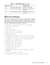
...; Hard disk drive read failure • Hard disk failure • Incompatible Processor: CPU0 is B0 step or below • Incompatible Processor: CPU1 is B0 step or below • Incompatible Processors: Cache sizes different • Keyboard clock line failure • Keyboard controller failure • Keyboard data line failure • Keyboard stuck key failure • No timer tick interrupt • Shutdown failure • Terminator/processor card not installed! When a fatal error occurs, the system usually cannot be rebooted...
...; Hard disk drive read failure • Hard disk failure • Incompatible Processor: CPU0 is B0 step or below • Incompatible Processor: CPU1 is B0 step or below • Incompatible Processors: Cache sizes different • Keyboard clock line failure • Keyboard controller failure • Keyboard data line failure • Keyboard stuck key failure • No timer tick interrupt • Shutdown failure • Terminator/processor card not installed! When a fatal error occurs, the system usually cannot be rebooted...
Service Manual
Page 38
... drive 1 seek failure Diskette read error from using available memory. System Error Messages Message Definition Probable Causes Address mark not found Attachment failed to respond BIOS found faulty disk sector or could not locate specific sector or track. Diskette drive or harddisk drive controller cannot send data to read error. not exist or is not in System Setup program, loose diskette/tape drive interface cable, or loose power cable...
... drive 1 seek failure Diskette read error from using available memory. System Error Messages Message Definition Probable Causes Address mark not found Attachment failed to respond BIOS found faulty disk sector or could not locate specific sector or track. Diskette drive or harddisk drive controller cannot send data to read error. not exist or is not in System Setup program, loose diskette/tape drive interface cable, or loose power cable...
Service Manual
Page 39
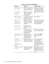
...Beep Codes and Error Messages 3-5 Diskette write protected Diskette write-protect feature activated. Incompatible Processor: CPU0 is B0 step or below Unsupported version of the ure keyboard controller malfunctioned. Incorrect configuration settings in diskette drive. on system board. Hard disk controller failure Hard disk drive read failure Hard disk failure Hard-disk drive failed to diskette controller. Table 3-2. Drive not ready Diskette missing from or improperly inserted in System Setup program, improperly connected hard-disk drive cable, faulty hard-disk...
...Beep Codes and Error Messages 3-5 Diskette write protected Diskette write-protect feature activated. Incompatible Processor: CPU0 is B0 step or below Unsupported version of the ure keyboard controller malfunctioned. Incorrect configuration settings in diskette drive. on system board. Hard disk controller failure Hard disk drive read failure Hard disk failure Hard-disk drive failed to diskette controller. Table 3-2. Drive not ready Diskette missing from or improperly inserted in System Setup program, improperly connected hard-disk drive cable, faulty hard-disk...
Service Manual
Page 43
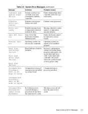
... in card. Beep Codes and Error Messages 3-9 System Error Messages (continued) Message Definition Probable Causes Sector not found MS-DOS unable to locate specific track on diskette kette or hard-disk drive. Defective diskette or hard-disk drive. Terminator/ processor card not installed! System does not have terminator or add-in protected mode Keyboard/mouse controller malfunctioning, or one or both thermal probes are nonoperational. Improperly seated DIMMs or faulty keyboard/mouse controller chip...
... in card. Beep Codes and Error Messages 3-9 System Error Messages (continued) Message Definition Probable Causes Sector not found MS-DOS unable to locate specific track on diskette kette or hard-disk drive. Defective diskette or hard-disk drive. Terminator/ processor card not installed! System does not have terminator or add-in protected mode Keyboard/mouse controller malfunctioning, or one or both thermal probes are nonoperational. Improperly seated DIMMs or faulty keyboard/mouse controller chip...
Service Manual
Page 60
... Dell OptiPlex GXpro Systems Service Manual System Board Components The subsections that follow contain procedures for removing system board components. microphone jack (NIC-IN) speaker-out jack (SPKR-OUT) line-in jack (LINE-IN) riser board power connector (RSR PWR1) riser board connector (RISER) riser board power connector (RSR PWR2) NIC connector (ENET) USB connectors(2) (USB) serial port 2 connector (SERIAL2) keyboard/mouse connectors (stacked) (KYBD/MOUSE) serial port 1/parallel port connectors (stacked) (PARALLEL/SERIAL) microprocessor fan connector (FAN) battery socket (BATTERY...
... Dell OptiPlex GXpro Systems Service Manual System Board Components The subsections that follow contain procedures for removing system board components. microphone jack (NIC-IN) speaker-out jack (SPKR-OUT) line-in jack (LINE-IN) riser board power connector (RSR PWR1) riser board connector (RISER) riser board power connector (RSR PWR2) NIC connector (ENET) USB connectors(2) (USB) serial port 2 connector (SERIAL2) keyboard/mouse connectors (stacked) (KYBD/MOUSE) serial port 1/parallel port connectors (stacked) (PARALLEL/SERIAL) microprocessor fan connector (FAN) battery socket (BATTERY...
Service Manual
Page 72
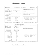
...: seconds) for the internal clock/ calendar. System Setup Screens Page 1 of 2 Dell Computer Corporation System OptiPlex GXpro 200 Setup BIOS Version: XXX Keyboard Errors: Report System Password: Not Enabled Password Status: Unlocked Boot Sequence: Diskette First Setup Password: Not Enabled Auto Power On: Mon-Fri 07:30 Power Management: Regular Integrated Devices Sound: On NIC: On Mouse: On Serial Port 1: Auto Serial Port 2: Auto Parallel Port: 378h Parallel Mode: AT IDE Hard Disk: Auto Diskette: Auto USB: On Speakers: On This category determines...
...: seconds) for the internal clock/ calendar. System Setup Screens Page 1 of 2 Dell Computer Corporation System OptiPlex GXpro 200 Setup BIOS Version: XXX Keyboard Errors: Report System Password: Not Enabled Password Status: Unlocked Boot Sequence: Diskette First Setup Password: Not Enabled Auto Power On: Mon-Fri 07:30 Power Management: Regular Integrated Devices Sound: On NIC: On Mouse: On Serial Port 1: Auto Serial Port 2: Auto Parallel Port: 378h Parallel Mode: AT IDE Hard Disk: Auto Diskette: Auto USB: On Speakers: On This category determines...
Service Manual
Page 77
... 1-4 add-in card, removal, 4-24 audio controller, 1-6 CD-ROM connector, 1-12 drives, 4-11 chassis, 1-4 computer, technical specifications, 1-16 configuration jumpers, location, 1-12, 4-16 connectors location on back of system unit, 1-4 location on system board, 1-12, 4-16 cover, system unit, removal, 4-4 B battery illustrated, 4-25 removing and replacing, 4-25 socket, 1-12, 4-16 beep codes, 3-1 BIOS chip, 1-12, 4-16 boot routine, observing when trouble- shooting, 2-3 bracket hard-disk drive, 1-4, 4-12 C cables DC power, 1-4, 1-10 diskette/tape drive interface, 1-4 EIDE, 4-9 card-slot opening...
... 1-4 add-in card, removal, 4-24 audio controller, 1-6 CD-ROM connector, 1-12 drives, 4-11 chassis, 1-4 computer, technical specifications, 1-16 configuration jumpers, location, 1-12, 4-16 connectors location on back of system unit, 1-4 location on system board, 1-12, 4-16 cover, system unit, removal, 4-4 B battery illustrated, 4-25 removing and replacing, 4-25 socket, 1-12, 4-16 beep codes, 3-1 BIOS chip, 1-12, 4-16 boot routine, observing when trouble- shooting, 2-3 bracket hard-disk drive, 1-4, 4-12 C cables DC power, 1-4, 1-10 diskette/tape drive interface, 1-4 EIDE, 4-9 card-slot opening...
Service Manual
Page 79
... power indicator, 1-4 power input connectors, 1-12, 4-16 power supply, 1-8 cable configuration, 1-10 DC voltage ranges, 1-8 illustrated, 1-10 removal, 4-14 precautions, 4-2 R reset button location, 1-4 removal, 4-5 resource conflicts eliminating, 2-5 riser board connector, 1-12 power connector, 1-12 removal, 4-19 P padlock, 4-4 PANEL connector, 4-16 Panel connector, 1-12 parallel port connector location, 1-4, 1-12, 4-16 PCI expansion cards, 1-5, 1-12, 4-16, 4-17, 4-18 PCI video card, 1-6 S secondary microprocessor, 4-23 serial port connectors, location, 1-4 SMART support, 1-8 sockets battery...
... power indicator, 1-4 power input connectors, 1-12, 4-16 power supply, 1-8 cable configuration, 1-10 DC voltage ranges, 1-8 illustrated, 1-10 removal, 4-14 precautions, 4-2 R reset button location, 1-4 removal, 4-5 resource conflicts eliminating, 2-5 riser board connector, 1-12 power connector, 1-12 removal, 4-19 P padlock, 4-4 PANEL connector, 4-16 Panel connector, 1-12 parallel port connector location, 1-4, 1-12, 4-16 PCI expansion cards, 1-5, 1-12, 4-16, 4-17, 4-18 PCI video card, 1-6 S secondary microprocessor, 4-23 serial port connectors, location, 1-4 SMART support, 1-8 sockets battery...


