
User Guide
Page 17
...power supply out of the bay. If you are replacing it for your configuration. 2. Remove the front bezel as instructed in a 5.25-inch drive bay, perform the following steps. To do so, see Figure 2). 6. Figure 1. Attaching the Drive Bracket to Contents Page Diskette, Tape, and CD-ROM Drives: Dell™ OptiPlex™ GX300.... Attach the drive bracket to use. Squeeze the metal tabs that secure the drive to the bracket (see "Rotating the Power Supply Away From the System Board." Removing a Drive 1 Bracket tabs (2) If a drive is configured for the Cable Select setting...
...power supply out of the bay. If you are replacing it for your configuration. 2. Remove the front bezel as instructed in a 5.25-inch drive bay, perform the following steps. To do so, see Figure 2). 6. Figure 1. Attaching the Drive Bracket to Contents Page Diskette, Tape, and CD-ROM Drives: Dell™ OptiPlex™ GX300.... Attach the drive bracket to use. Squeeze the metal tabs that secure the drive to the bracket (see "Rotating the Power Supply Away From the System Board." Removing a Drive 1 Bracket tabs (2) If a drive is configured for the Cable Select setting...

User Guide
Page 36
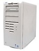
Back to Contents Page Inside Your Computer: Dell™ OptiPlex™ GX300 System User's Guide Overview Internal Views System Board Components System Board Jumpers System Board Labels Removing and Replacing the AGP Card Brace Rotating the Power Supply Away From the System Board Removing and...Figure 1 shows a side view of your computer and may be used as a reference before performing an upgrade procedure. Inside the Chassis 1 Power supply 2 AC power receptacle 3 I/O panel connectors 4 expansion card slots 5 Padlock ring 6 Security cable slot 7 AGP card brace 8 Drive interface cable 9 ...
Back to Contents Page Inside Your Computer: Dell™ OptiPlex™ GX300 System User's Guide Overview Internal Views System Board Components System Board Jumpers System Board Labels Removing and Replacing the AGP Card Brace Rotating the Power Supply Away From the System Board Removing and...Figure 1 shows a side view of your computer and may be used as a reference before performing an upgrade procedure. Inside the Chassis 1 Power supply 2 AC power receptacle 3 I/O panel connectors 4 expansion card slots 5 Padlock ring 6 Security cable slot 7 AGP card brace 8 Drive interface cable 9 ...

User Guide
Page 40
... until it locks in "Removing the Computer Cover." 2. Disconnect the AC power cable from the AC power receptacle on the system board, you first must first remove the front bezel. Free the power supply from the chassis. Remove the computer cover as instructed in its extended position...must remove the computer cover (see "Safety First-For You and Your Computer." 1. Rotating the Power Supply 1 Power supply 2 Release latch 3 AC power cable 4 Securing tab 5 DC power cable 3. Rotating the Power Supply Away From the System Board To access some drive bays, you remove the computer cover, see...
... until it locks in "Removing the Computer Cover." 2. Disconnect the AC power cable from the AC power receptacle on the system board, you first must first remove the front bezel. Free the power supply from the chassis. Remove the computer cover as instructed in its extended position...must remove the computer cover (see "Safety First-For You and Your Computer." 1. Rotating the Power Supply 1 Power supply 2 Release latch 3 AC power cable 4 Securing tab 5 DC power cable 3. Rotating the Power Supply Away From the System Board To access some drive bays, you remove the computer cover, see...

User Guide
Page 48
.... Turn off the system, including any of either the boot routine or the Dell Diagnostics, or if a drive is not operating correctly, perform the following steps: 1. If any attached peripherals, and disconnect all the AC power cables from the power supply are firmly connected to an electrical outlet, and turn off the system, including...
.... Turn off the system, including any of either the boot routine or the Dell Diagnostics, or if a drive is not operating correctly, perform the following steps: 1. If any attached peripherals, and disconnect all the AC power cables from the power supply are firmly connected to an electrical outlet, and turn off the system, including...

User Guide
Page 53
...use for energy efficiency. Back to Contents Page For more information about the WBEM core components and how to install them, see the online Dell OpenManage Client Instrumentation Version 5.0 User's Guide. Figure 1. Computer users can reduce emissions of carbon dioxide, the gas primarily responsible for energyefficient.... Temperature and Voltage Monitoring Your system includes temperature and voltage probes to sense when the system becomes overheated or the power supply voltage is stored in the cost of ownership Management Information Format (coo.mif) file on weekends.
...use for energy efficiency. Back to Contents Page For more information about the WBEM core components and how to install them, see the online Dell OpenManage Client Instrumentation Version 5.0 User's Guide. Figure 1. Computer users can reduce emissions of carbon dioxide, the gas primarily responsible for energyefficient.... Temperature and Voltage Monitoring Your system includes temperature and voltage probes to sense when the system becomes overheated or the power supply voltage is stored in the cost of ownership Management Information Format (coo.mif) file on weekends.

User Guide
Page 54
...RIMM that identifies the number of 16 memory devices. You can increase system memory up to Contents Page System Memory: Dell™ OptiPlex™ GX300 System User's Guide Overview Installing RIMMs Removing RIMMs Overview Before you install new memory modules, download the most recent .... Figure 1. CAUTION: To avoid the possibility of memory devices in RIMM For optimum operation, Dell recommends that occupy sockets in "Safety First-For You and Your Computer. Rotate the power supply as described in "Removing and Replacing the Computer Cover." 2. You can also determine the number...
...RIMM that identifies the number of 16 memory devices. You can increase system memory up to Contents Page System Memory: Dell™ OptiPlex™ GX300 System User's Guide Overview Installing RIMMs Removing RIMMs Overview Before you install new memory modules, download the most recent .... Figure 1. CAUTION: To avoid the possibility of memory devices in RIMM For optimum operation, Dell recommends that occupy sockets in "Safety First-For You and Your Computer. Rotate the power supply as described in "Removing and Replacing the Computer Cover." 2. You can also determine the number...

User Guide
Page 55
...on. Removing a RIMM 1 Securing clips (2) Back to run the setup utility 7. Rotate the power supply back into position, making sure that they are operating properly. Remove the computer cover, rotate the power supply, and check the installed RIMMs to exit System Setup. 11. NOTE: If a setup password ...has been assigned by changing Chassis Intrusion to appear on resetting the chassis intrusion detector. 10. Run the Dell Diagnostics to verify that the new...
...on. Removing a RIMM 1 Securing clips (2) Back to run the setup utility 7. Rotate the power supply back into position, making sure that they are operating properly. Remove the computer cover, rotate the power supply, and check the installed RIMMs to exit System Setup. 11. NOTE: If a setup password ...has been assigned by changing Chassis Intrusion to appear on resetting the chassis intrusion detector. 10. Run the Dell Diagnostics to verify that the new...

User Guide
Page 61
...and no beep code but the system locks up during POST Hard-Disk Drive LED Code Blank Solid green N/A N/A N/A N/A Cause System power supply failure. A device on the system board may be faulty. The monitor or the graphics card may be faulty. An integrated system board ... diagnosing the beep code. See "Troubleshooting the Monitor." Back to Contents Page See "Getting Help" for instructions on obtaining technical assistance. The power indicator light-emitting diode (LED) and the hard-disk drive LED on the front of the computer emit diagnostic codes that each microprocessor is ...
...and no beep code but the system locks up during POST Hard-Disk Drive LED Code Blank Solid green N/A N/A N/A N/A Cause System power supply failure. A device on the system board may be faulty. The monitor or the graphics card may be faulty. An integrated system board ... diagnosing the beep code. See "Troubleshooting the Monitor." Back to Contents Page See "Getting Help" for instructions on obtaining technical assistance. The power indicator light-emitting diode (LED) and the hard-disk drive LED on the front of the computer emit diagnostic codes that each microprocessor is ...

User Guide
Page 62
Back to Contents Page Microprocessor: Dell™ OptiPlex™ GX300 System User's Guide Adding a Second Microprocessor Upgrading an Existing Microprocessor Adding a Second Microprocessor Use the following procedure to...Dell recommends that the securing tab snaps into position, making sure that only a technically knowledgeable person perform this LED, see "Safety First-For You and Your Computer." NOTE: Before disconnecting a peripheral from the system or removing a component from the secondary single-edge connector (SEC) cartridge connector (labeled "PROC_1"). Rotate the power supply...
Back to Contents Page Microprocessor: Dell™ OptiPlex™ GX300 System User's Guide Adding a Second Microprocessor Upgrading an Existing Microprocessor Adding a Second Microprocessor Use the following procedure to...Dell recommends that the securing tab snaps into position, making sure that only a technically knowledgeable person perform this LED, see "Safety First-For You and Your Computer." NOTE: Before disconnecting a peripheral from the system or removing a component from the secondary single-edge connector (SEC) cartridge connector (labeled "PROC_1"). Rotate the power supply...

User Guide
Page 63
... has turned off. Squeeze in "Rotating the Power Supply Away From the System Board." 3. Microprocessor Removal 1 Airflow shroud 2 Processor/heat sink assembly 3 Guide bracket 4 Second processor 5 Cooling fan 5. Run the Dell Diagnostics to verify that the securing tab snaps into... its connector. Press the processor firmly into place. Rotate the power supply back into the system board connector. Insert the new microprocessor into position...
... has turned off. Squeeze in "Rotating the Power Supply Away From the System Board." 3. Microprocessor Removal 1 Airflow shroud 2 Processor/heat sink assembly 3 Guide bracket 4 Second processor 5 Cooling fan 5. Run the Dell Diagnostics to verify that the securing tab snaps into... its connector. Press the processor firmly into place. Rotate the power supply back into the system board connector. Insert the new microprocessor into position...

User Guide
Page 86
... for diagnostics green LED green LED for 10-Mb operation; orange LED for 100-Mb operation yellow LED Power DC power supply: Wattage Heat dissipation Voltage Backup battery Physical Height Width Depth Weight Environmental Temperature: 230 W 913 British thermal units (BTUs) (fully loaded system without monitor) 90 ...
... for diagnostics green LED green LED for 10-Mb operation; orange LED for 100-Mb operation yellow LED Power DC power supply: Wattage Heat dissipation Voltage Backup battery Physical Height Width Depth Weight Environmental Temperature: 230 W 913 British thermal units (BTUs) (fully loaded system without monitor) 90 ...


