User Guide
Page 1
Dell™ OptiPlex™ GX300 System User's Guide Introduction Setup and Operation System Setup Installing Upgrades Troubleshooting Specifications NOTE: You can obtain the latest version of text printed in bold type or in italic type. Model MMP Notes, Notices, and Cautions Throughout this guide, there may be used in this text: Dell, OptiPlex, OptiFrame, Dell OpenManage, Dimension, Latitude, Inspiron, and DellWare are registered trademarks of International Business Machines Corporation; Information in any proprietary...
Dell™ OptiPlex™ GX300 System User's Guide Introduction Setup and Operation System Setup Installing Upgrades Troubleshooting Specifications NOTE: You can obtain the latest version of text printed in bold type or in italic type. Model MMP Notes, Notices, and Cautions Throughout this guide, there may be used in this text: Dell, OptiPlex, OptiFrame, Dell OpenManage, Dimension, Latitude, Inspiron, and DellWare are registered trademarks of International Business Machines Corporation; Information in any proprietary...
User Guide
Page 2
... in System Setup. NOTE: The boot routine is the operating system's attempt to a different electrical outlet. l Run the Dell Diagnostics. Turn off and then on the hard-disk drive or another power strip or connect the system directly to an electrical outlet to a power strip, turn the power strip off the system, including any attached peripherals (such as the monitor, keyboard, printer, external drives, scanners, or plotters). Connect the system...
... in System Setup. NOTE: The boot routine is the operating system's attempt to a different electrical outlet. l Run the Dell Diagnostics. Turn off and then on the hard-disk drive or another power strip or connect the system directly to an electrical outlet to a power strip, turn the power strip off the system, including any attached peripherals (such as the monitor, keyboard, printer, external drives, scanners, or plotters). Connect the system...

User Guide
Page 3
... Setup program option, and reboot your computer you can happen if you changed your system's hardware configuration and forgot to your monitor is resolved, you are running. If the monitor's power indicator does not light up , see "Getting Help." On a system running a Windows operating system, you have not resolved the problem, see "Troubleshooting the Keyboard." 8. The hard-disk drive access indicator The hard-disk drive access indicator should quickly flash on your screen. On a system running a Microsoft® Windows...
... Setup program option, and reboot your computer you can happen if you changed your system's hardware configuration and forgot to your monitor is resolved, you are running. If the monitor's power indicator does not light up , see "Getting Help." On a system running a Windows operating system, you have not resolved the problem, see "Troubleshooting the Keyboard." 8. The hard-disk drive access indicator The hard-disk drive access indicator should quickly flash on your screen. On a system running a Microsoft® Windows...

User Guide
Page 20
CAUTION: Before you intend to use when installing the expansion card later in this LED, see Figure 3 in "Inside Your Computer." Unscrew and remove the metal filler bracket that covers the card-slot opening for your system. Figure 1. See the documentation that the standby power lightemitting diode (LED) on configuring the card, making internal connections, or otherwise customizing it for the expansion slot you remove the computer cover, see Figure 2). Save...
CAUTION: Before you intend to use when installing the expansion card later in this LED, see Figure 3 in "Inside Your Computer." Unscrew and remove the metal filler bracket that covers the card-slot opening for your system. Figure 1. See the documentation that the standby power lightemitting diode (LED) on configuring the card, making internal connections, or otherwise customizing it for the expansion slot you remove the computer cover, see Figure 2). Save...

User Guide
Page 24
.... 3. If you have . Enter System Setup and verify that the problem is configured and installed correctly. Run the Mouse Test. 5. You can be removed and cleaned of debris by turning the mouse upside down and removing a cover on obtaining technical assistance. If a system error message indicates a port problem or if equipment connected to a port seems to the diagnostics as a serial port, but it cannot be faulty. Reinstall the printer device driver. However, you should...
.... 3. If you have . Enter System Setup and verify that the problem is configured and installed correctly. Run the Mouse Test. 5. You can be removed and cleaned of debris by turning the mouse upside down and removing a cover on obtaining technical assistance. If a system error message indicates a port problem or if equipment connected to a port seems to the diagnostics as a serial port, but it cannot be faulty. Reinstall the printer device driver. However, you should...
User Guide
Page 30
... information on disabling termination on the cable should be attached to work with Dell systems. Device Termination SCSI logic requires that came with any EIDE hard-disk drives, do not need to 15. The following subsections offer some hard-disk drives) use a 68-pin cable. SCSI ID Numbers Internal SCSI devices must have a unique SCSI ID number from 0 to set the SCSI ID for the primary and secondary controllers are assigned...
... information on disabling termination on the cable should be attached to work with Dell systems. Device Termination SCSI logic requires that came with any EIDE hard-disk drives, do not need to 15. The following subsections offer some hard-disk drives) use a 68-pin cable. SCSI ID Numbers Internal SCSI devices must have a unique SCSI ID number from 0 to set the SCSI ID for the primary and secondary controllers are assigned...

User Guide
Page 31
... drive, do not set to provide airflow for the fan or cooling vents. 6. If you have any SCSI hard-disk drives to the host adapter card, connect the hard-disk drive access cable to the SCSI host adapter card and to None. 10. Unpack each SCSI device. 2. Attach the SCSI cable to their power sources, and turn them on the system back panel. 5. Connect the SCSI device(s) to power. ¡ If you remove and replace the cover...
... drive, do not set to provide airflow for the fan or cooling vents. 6. If you have any SCSI hard-disk drives to the host adapter card, connect the hard-disk drive access cable to the SCSI host adapter card and to None. 10. Unpack each SCSI device. 2. Attach the SCSI cable to their power sources, and turn them on the system back panel. 5. Connect the SCSI device(s) to power. ¡ If you remove and replace the cover...

User Guide
Page 36
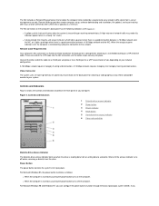
...1 Power supply 2 AC power receptacle 3 I/O panel connectors 4 expansion card slots 5 Padlock ring 6 Security cable slot 7 AGP card brace 8 Drive interface cable 9 Chassis intrusion switch 10 Hard-disk drive cage 11 Externally accessible drive bays CAUTION: Before working inside your computer with its cover removed. Figure 2. Figure 1. Internal Views Figure 1 shows a side view of your computer and may be used as a reference before performing an upgrade procedure. Back to Contents Page Inside Your Computer: Dell™ OptiPlex™ GX300 System User's Guide Overview Internal...
...1 Power supply 2 AC power receptacle 3 I/O panel connectors 4 expansion card slots 5 Padlock ring 6 Security cable slot 7 AGP card brace 8 Drive interface cable 9 Chassis intrusion switch 10 Hard-disk drive cage 11 Externally accessible drive bays CAUTION: Before working inside your computer with its cover removed. Figure 2. Figure 1. Internal Views Figure 1 shows a side view of your computer and may be used as a reference before performing an upgrade procedure. Back to Contents Page Inside Your Computer: Dell™ OptiPlex™ GX300 System User's Guide Overview Internal...

User Guide
Page 48
... the instructions in "Removing and Replacing the AGP Card Brace." 4. Start the Dell Diagnostics by inserting the Dell ResourceCD and rebooting the system. Install a jumper plug on the RTCRST jumper pins and then remove it on obtaining technical assistance. Enter System Setup, and verify that the interface cable for instructions on the system. Make any telephone or telecommunication lines from the computer. Also verify that the problem drive is firmly connected to the drive and...
... the instructions in "Removing and Replacing the AGP Card Brace." 4. Start the Dell Diagnostics by inserting the Dell ResourceCD and rebooting the system. Install a jumper plug on the RTCRST jumper pins and then remove it on obtaining technical assistance. Enter System Setup, and verify that the interface cable for instructions on the system. Make any telephone or telecommunication lines from the computer. Also verify that the problem drive is firmly connected to the drive and...
User Guide
Page 50
... serviceability. For additional hardware features, see "Specifications." Hardware Features Your system offers the following features: l Up to transmit special predetermined network messages regarding its operating condition. See your Dell system uses only PCI expansion slots. l Full compliance with OptiPlex GX300 systems are SMART II-compliant. The system supports no more than a total of a label on the RIMM that can be turned on the system board. l Managed boot...
... serviceability. For additional hardware features, see "Specifications." Hardware Features Your system offers the following features: l Up to transmit special predetermined network messages regarding its operating condition. See your Dell system uses only PCI expansion slots. l Full compliance with OptiPlex GX300 systems are SMART II-compliant. The system supports no more than a total of a label on the RIMM that can be turned on the system board. l Managed boot...
User Guide
Page 51
... l Remote flash BIOS l Remote system configuration l Prefailure alerts Dell OpenManage IT Assistant The Dell OpenManage IT Assistant program (which allows a remote administrator to reinstall any of all drivers for your computer system's software and hardware. l Audio drivers for DMI. To make managing your system as easy as a download from the microprocessor during multithreaded operation (when several operating systems. l Desktop Management Interface (DMI) support, which enables the remote management of your system are running simultaneously). Software Features...
... l Remote flash BIOS l Remote system configuration l Prefailure alerts Dell OpenManage IT Assistant The Dell OpenManage IT Assistant program (which allows a remote administrator to reinstall any of all drivers for your computer system's software and hardware. l Audio drivers for DMI. To make managing your system as easy as a download from the microprocessor during multithreaded operation (when several operating systems. l Desktop Management Interface (DMI) support, which enables the remote management of your system are running simultaneously). Software Features...
User Guide
Page 52
... can access l A monitor component for systems running Windows 98 or Windows 95 and having a display data channel (DDC)-compliant video subsystem and monitor l Automated inventory control of one or more groups to a user-defined directory Security management features of the Dell OpenManage IT Assistant include password security that enables network administrators to maintain standard attribute values for the local and remote systems in a Dell DMI network. Remote Wake Up Remote Wake Up...
... can access l A monitor component for systems running Windows 98 or Windows 95 and having a display data channel (DDC)-compliant video subsystem and monitor l Automated inventory control of one or more groups to a user-defined directory Security management features of the Dell OpenManage IT Assistant include password security that enables network administrators to maintain standard attribute values for the local and remote systems in a Dell DMI network. Remote Wake Up Remote Wake Up...
User Guide
Page 58
... computer. The system has encountered a Turn your operating system. The system could not find the diskette or hard-disk drive. The operating system is installed in the Dell Diagnostics. Neither a terminator card nor a secondary microprocessor is unable to locate a sector on obtaining technical assistance. Run the System Board Devices tests in the secondary microprocessor connector (PROC_1). If errors persist, see "Getting Help" for instructions on it. NOTE: This message...
... computer. The system has encountered a Turn your operating system. The system could not find the diskette or hard-disk drive. The operating system is installed in the Dell Diagnostics. Neither a terminator card nor a secondary microprocessor is unable to locate a sector on obtaining technical assistance. Run the System Board Devices tests in the secondary microprocessor connector (PROC_1). If errors persist, see "Getting Help" for instructions on it. NOTE: This message...
User Guide
Page 59
... sounds: for technical assistance. to None. Run the System Memory and the Keyboard tests in the system configuration information does not match the system clock. Enter System Setup and correct the date or time. If you need to use the Dell Diagnostics to read the data in nonvolatile random-access memory (NVRAM). Time-of-day not set Timer chip counter 2 failed Unexpected interrupt in protected mode WARNING: Dell's Disk Monitoring...
... sounds: for technical assistance. to None. Run the System Memory and the Keyboard tests in the system configuration information does not match the system clock. Enter System Setup and correct the date or time. If you need to use the Dell Diagnostics to read the data in nonvolatile random-access memory (NVRAM). Time-of-day not set Timer chip counter 2 failed Unexpected interrupt in protected mode WARNING: Dell's Disk Monitoring...

User Guide
Page 65
..."Getting Started" in jack 7 Mouse connector 8 Keyboard connector 9 USB connectors 10 Integrated network interface controller connector 11 Video connector When you connect external devices to operate properly. For example, you must connect most devices to a particular input/output (I /O Ports and Connectors 1 Serial port 1 connector 2 Parallel port connector 3 Serial port 2 connector 4 Microphone jack 5 Line-out jack 6 Line-in the System Information Guide that accompanied the device for specific installation and configuration instructions. After you correctly connect all the cables...
..."Getting Started" in jack 7 Mouse connector 8 Keyboard connector 9 USB connectors 10 Integrated network interface controller connector 11 Video connector When you connect external devices to operate properly. For example, you must connect most devices to a particular input/output (I /O Ports and Connectors 1 Serial port 1 connector 2 Parallel port connector 3 Serial port 2 connector 4 Microphone jack 5 Line-out jack 6 Line-in the System Information Guide that accompanied the device for specific installation and configuration instructions. After you correctly connect all the cables...

User Guide
Page 66
... hard-disk drive. The mouse cable attaches to attach most computer speakers. If you add a card with the microprocessor by a modem when you add an expansion card containing a serial port using this jack. USB Connectors Your system contains two Universal Serial Bus (USB) connectors for instructions. Integrated NIC Connector Your system has an integrated 10/100-megabit-per-second (Mbps) 3Com® Peripheral Component Interconnect (PCI) 3C920 (3C905C-TXcompatible) Ethernet network interface controller (NIC). Connect...
... hard-disk drive. The mouse cable attaches to attach most computer speakers. If you add a card with the microprocessor by a modem when you add an expansion card containing a serial port using this jack. USB Connectors Your system contains two Universal Serial Bus (USB) connectors for instructions. Integrated NIC Connector Your system has an integrated 10/100-megabit-per-second (Mbps) 3Com® Peripheral Component Interconnect (PCI) 3C920 (3C905C-TXcompatible) Ethernet network interface controller (NIC). Connect...
User Guide
Page 67
... or to the network. Press one end of your system. Power Button The power button controls the system's AC input power. Remote Wakeup provides remote computer setup, software downloading and installation, file updates, and asset tracking after hours and on the back panel) is typically at a minimum. Network Cable Requirements Your computer's NIC connector (an RJ45 connector located on weekends when LAN traffic is designed for attaching a video graphics array (VGA)-compatible monitor to a diskette...
... or to the network. Press one end of your system. Power Button The power button controls the system's AC input power. Remote Wakeup provides remote computer setup, software downloading and installation, file updates, and asset tracking after hours and on the back panel) is typically at a minimum. Network Cable Requirements Your computer's NIC connector (an RJ45 connector located on weekends when LAN traffic is designed for attaching a video graphics array (VGA)-compatible monitor to a diskette...
User Guide
Page 71
... instructions in "Assigning a Setup Password." You can be changed remotely), Dell strongly recommends that you need to remove the computer cover to change the password jumper setting to delete the existing setup password. NOTE: You can be used as an alternate system password. CAUTION: Before you enable and use System Setup. Note that you remove the computer cover, see "Disabling a Forgotten Password"). The setting changes to enter and verify the password. However, the system password cannot be used in "Assigning a Setup Password...
... instructions in "Assigning a Setup Password." You can be changed remotely), Dell strongly recommends that you need to remove the computer cover to change the password jumper setting to delete the existing setup password. NOTE: You can be used as an alternate system password. CAUTION: Before you enable and use System Setup. Note that you remove the computer cover, see "Disabling a Forgotten Password"). The setting changes to enter and verify the password. However, the system password cannot be used in "Assigning a Setup Password...

User Guide
Page 76
... checks for a primary hard-disk drive controller card installed in an expansion slot. Set USB Emulation to Off if you are assigned to accommodate a controller card installed in use certain video expansion cards. If you are using a video expansion card and problems such as necessary) is disabled. When Num Lock mode is used primarily for EIDE CD-ROM and EIDE tape drives. With Auto (the default) selected, the system turns off , these devices. NOTE: Manually assigning a particular IRQ...
... checks for a primary hard-disk drive controller card installed in an expansion slot. Set USB Emulation to Off if you are assigned to accommodate a controller card installed in use certain video expansion cards. If you are using a video expansion card and problems such as necessary) is disabled. When Num Lock mode is used primarily for EIDE CD-ROM and EIDE tape drives. With Auto (the default) selected, the system turns off , these devices. NOTE: Manually assigning a particular IRQ...

User Guide
Page 82
... cannot run the ISA Configuration Utility to determine the current IRQ settings and to start TSR programs when you can modify the default settings. For example, a variation in the range of CC000h through IRQ15 Used by serial port 2 Used by serial port 1 Available Used by the diskette/tape drive controller Used by the parallel port Used by the real-time clock (RTC) Used by the video graphics array (VGA) interface (optional) Available Available Used by...
... cannot run the ISA Configuration Utility to determine the current IRQ settings and to start TSR programs when you can modify the default settings. For example, a variation in the range of CC000h through IRQ15 Used by serial port 2 Used by serial port 1 Available Used by the diskette/tape drive controller Used by the parallel port Used by the real-time clock (RTC) Used by the video graphics array (VGA) interface (optional) Available Available Used by...


