Service Manual
Page 2
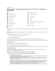
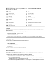
... from electrostatic discharge (ESD). l You can replace or reinstall a part by performing the removal procedure in the Dell OptiPlex low-profile chassis GX200 system. Also, disconnect any procedure in this file require the use of one or more of the following tools:.... Removing and Replacing Parts: Dell™ OptiPlex™ GX200 Systems Service Manual Overview Recommended Tools Precautionary Measures Internal Views Computer Cover Eject, Power, and Reset Buttons Front-Panel Inserts Control Panel Chassis Intrusion Switch Drives System Power Supply Expansion-Card Cage Riser Boards...
... from electrostatic discharge (ESD). l You can replace or reinstall a part by performing the removal procedure in the Dell OptiPlex low-profile chassis GX200 system. Also, disconnect any procedure in this file require the use of one or more of the following tools:.... Removing and Replacing Parts: Dell™ OptiPlex™ GX200 Systems Service Manual Overview Recommended Tools Precautionary Measures Internal Views Computer Cover Eject, Power, and Reset Buttons Front-Panel Inserts Control Panel Chassis Intrusion Switch Drives System Power Supply Expansion-Card Cage Riser Boards...
Service Manual
Page 3
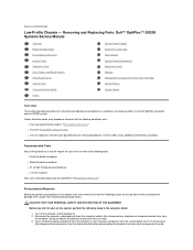
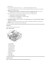
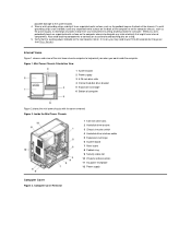
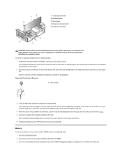
... wrist grounding strap, and clip it to an unpainted metal surface, such as the padlock loop on the computer chassis, such as the power supply, to discharge any unpainted metal surface on the back of the computer or on the back of the low-profile chassis to help you orient...to wait 10 to the system board. 4. Verify that might harm internal components. Low-Profile Chassis Orientation View 1 System board 2 Hard-disk drive 3 Power supply 4 Externally accessible drive bays Figure 2 shows the low-profile chassis with the cover removed. Figure 2. possible damage to 30 seconds for it is on a...
... wrist grounding strap, and clip it to an unpainted metal surface, such as the padlock loop on the computer chassis, such as the power supply, to discharge any unpainted metal surface on the back of the computer or on the back of the low-profile chassis to help you orient...to wait 10 to the system board. 4. Verify that might harm internal components. Low-Profile Chassis Orientation View 1 System board 2 Hard-disk drive 3 Power supply 4 Externally accessible drive bays Figure 2 shows the low-profile chassis with the cover removed. Figure 2. possible damage to 30 seconds for it is on a...
Service Manual
Page 9
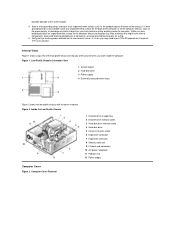
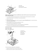
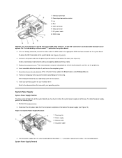
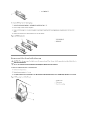
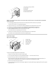
...the IDE1 connector on the system board. Disconnect the DC power cables from the back of the power supply. 2. If it is the primary drive, install your operating system. System Power Supply Figure 13. 1 Power cable 2 EIDE interface cable 3 IDE1 connector on system ...update the appropriate Primary Drive option, 0 or 1 (see "System Board Components." 11. Power Supply Removal 1 AC power cord 2 AC power receptacle 3 Power supply 4 DC power cables 5 Securing screw To remove the system power supply, perform the following steps: 1. To locate the IDE1 connector on the system board, ...
...the IDE1 connector on the system board. Disconnect the DC power cables from the back of the power supply. 2. If it is the primary drive, install your operating system. System Power Supply Figure 13. 1 Power cable 2 EIDE interface cable 3 IDE1 connector on system ...update the appropriate Primary Drive option, 0 or 1 (see "System Board Components." 11. Power Supply Removal 1 AC power cord 2 AC power receptacle 3 Power supply 4 DC power cables 5 Securing screw To remove the system power supply, perform the following steps: 1. To locate the IDE1 connector on the system board, ...
Service Manual
Page 10
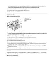
... 1. PCI Riser Board (Standard) It is flush with the tabs in the RISER connector on the back of the chassis. 4. Slide the power supply toward the front of the chassis. 4. Rotate the securing lever downward until it is important to route these cables properly when you replace them ...Boards The low-profile chassis has a standard PCI riser board (see Figure 15) or an optional PCI/ISA riser board (see Figure 14). Lift the power supply up and away from the system board and drives. Expansion-Card Cage Removal 1 Securing lever 2 Expansion-card cage 3 Slots (2) 4 Tabs (2) To remove...
... 1. PCI Riser Board (Standard) It is flush with the tabs in the RISER connector on the back of the chassis. 4. Slide the power supply toward the front of the chassis. 4. Rotate the securing lever downward until it is important to route these cables properly when you replace them ...Boards The low-profile chassis has a standard PCI riser board (see Figure 15) or an optional PCI/ISA riser board (see Figure 14). Lift the power supply up and away from the system board and drives. Expansion-Card Cage Removal 1 Securing lever 2 Expansion-card cage 3 Slots (2) 4 Tabs (2) To remove...
Service Manual
Page 15
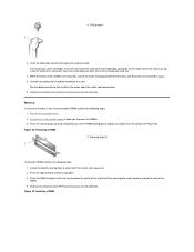
... snap open. 3. Memory To remove a Rambus in the connector, secure the card's mounting bracket to access the RIMMs. 3. Figure 22. Installing a RIMM Remove the system power supply to allow you to the chassis with the screw you insert the card into the expansion-card connector. Press the RIMM straight into the slot...
... snap open. 3. Memory To remove a Rambus in the connector, secure the card's mounting bracket to access the RIMMs. 3. Figure 22. Installing a RIMM Remove the system power supply to allow you to the chassis with the screw you insert the card into the expansion-card connector. Press the RIMM straight into the slot...
Service Manual
Page 20
...." If you perform any procedure in this file require the use a wrist grounding strap as explained in the Dell OptiPlex 200 midsize chassis system. Unless otherwise noted, each procedure assumes that the following steps in reverse order unless additional...of the chassis. Recommended Tools The procedures in "Precautionary Measures." Removing and Replacing Parts: Dell™ OptiPlex™ GX200 System Service Manual Overview System Power Supply Recommended Tools System Board Components Precautionary Measures Expansion Cards Computer Cover Riser Boards Internal View ...
...." If you perform any procedure in this file require the use a wrist grounding strap as explained in the Dell OptiPlex 200 midsize chassis system. Unless otherwise noted, each procedure assumes that the following steps in reverse order unless additional...of the chassis. Recommended Tools The procedures in "Precautionary Measures." Removing and Replacing Parts: Dell™ OptiPlex™ GX200 System Service Manual Overview System Power Supply Recommended Tools System Board Components Precautionary Measures Expansion Cards Computer Cover Riser Boards Internal View ...
Service Manual
Page 22
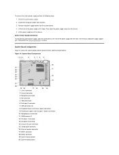
... Chassis intrusion switch 4 Drive interface cable 5 Expansion-card cage 6 Security cable slot 7 I/O ports and connectors 8 AC power receptacle 9 Padlock ring 10 Power supply 11 System board 12 Drive interface cable Front-Panel Inserts Figure 4. 5.25-Inch Front-Panel Insert Removal (cutaway view through ...top of the screen. Set Secondary Drive 0 or Secondary Drive 1, as appropriate, to Off. 6. Run the Dell Diagnostics to Enabled,...
... Chassis intrusion switch 4 Drive interface cable 5 Expansion-card cage 6 Security cable slot 7 I/O ports and connectors 8 AC power receptacle 9 Padlock ring 10 Power supply 11 System board 12 Drive interface cable Front-Panel Inserts Figure 4. 5.25-Inch Front-Panel Insert Removal (cutaway view through ...top of the screen. Set Secondary Drive 0 or Secondary Drive 1, as appropriate, to Off. 6. Run the Dell Diagnostics to Enabled,...
Service Manual
Page 25
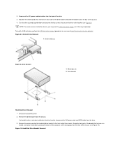
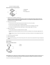
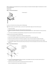
NOTE: For easier access inside the chassis, you may want to rotate the power supply out of the chassis. Figure 8. 5.25-Inch Drive Removal 1 Bracket tabs...wall of the way temporarily. If a hard-disk drive is already installed on the drive bracket, disconnect the DC power cable and EIDE cable from the back of the drive. 3. Drive Bracket 1 Metal tabs (2) 2 Drive bracket ... drive assembly upside down and unscrew the four screws that extend from the chassis. 2. Disconnect the DC power and data cables from the drive. 3. Remove the drive bracket from each side of the drive bracket and...
NOTE: For easier access inside the chassis, you may want to rotate the power supply out of the chassis. Figure 8. 5.25-Inch Drive Removal 1 Bracket tabs...wall of the way temporarily. If a hard-disk drive is already installed on the drive bracket, disconnect the DC power cable and EIDE cable from the back of the drive. 3. Drive Bracket 1 Metal tabs (2) 2 Drive bracket ... drive assembly upside down and unscrew the four screws that extend from the chassis. 2. Disconnect the DC power and data cables from the drive. 3. Remove the drive bracket from each side of the drive bracket and...
Service Manual
Page 27
... other end of the EIDE cable to your system. To rotate the power supply, perform the following steps: 1. System Power Supply Rotation 1 Securing tab 2 Power supply 3 Release latch 4 AC power cable 3. System Power Supply Removal 1 Interface connector 2 Power input connector on drive 3 Lip 4 Rail 5 IDE1 connector 6 IDE2 connector 7 DC power cable 8 EIDE cable NOTICE: You must match the colored strip on...
... other end of the EIDE cable to your system. To rotate the power supply, perform the following steps: 1. System Power Supply Rotation 1 Securing tab 2 Power supply 3 Release latch 4 AC power cable 3. System Power Supply Removal 1 Interface connector 2 Power input connector on drive 3 Lip 4 Rail 5 IDE1 connector 6 IDE2 connector 7 DC power cable 8 EIDE cable NOTICE: You must match the colored strip on...
Service Manual
Page 28
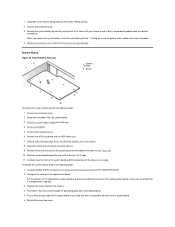
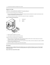
System Board Components Figure 14 shows the system board and the location of the power supply with the holes in the chassis and power supply support arm. To remove the system power supply, perform the following steps: 1. Rotate the system power supply. 2. Then perform the removal procedure in connector 2 Line-out connector 3 Microphone connector 4 NIC connector 5 Video connector 6 Serial...
System Board Components Figure 14 shows the system board and the location of the power supply with the holes in the chassis and power supply support arm. To remove the system power supply, perform the following steps: 1. Rotate the system power supply. 2. Then perform the removal procedure in connector 2 Line-out connector 3 Microphone connector 4 NIC connector 5 Video connector 6 Serial...
Service Manual
Page 32
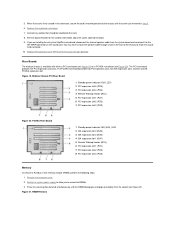
... the system power supply to allow you removed in the connector, secure the card's mounting bracket to the INT SPKR connector on the sound card. When the card is available with the screw you to the card. 8. If you are installing the entry-level OptiPlex sound card...). You may have to route the speaker cable through a hole in -line memory module (RIMM), perform the following steps: 1. Midsize Chassis PCI Riser Board 1 Standby power indicator (AUX_LED) 2 PCI expansion slot 5 (PCI5) 3 PCI expansion slot 4 (PCI4) 4 Remote Wakeup header (WOL) 5 PCI expansion slot 1 (PCI1) 6 PCI ...
... the system power supply to allow you removed in the connector, secure the card's mounting bracket to the INT SPKR connector on the sound card. When the card is available with the screw you to the card. 8. If you are installing the entry-level OptiPlex sound card...). You may have to route the speaker cable through a hole in -line memory module (RIMM), perform the following steps: 1. Midsize Chassis PCI Riser Board 1 Standby power indicator (AUX_LED) 2 PCI expansion slot 5 (PCI5) 3 PCI expansion slot 4 (PCI4) 4 Remote Wakeup header (WOL) 5 PCI expansion slot 1 (PCI1) 6 PCI ...
Service Manual
Page 33
... get extremely hot. Be sure that only a technically knowledgeable person perform this procedure. Remove the computer cover. 2. Figure 23. Rotate the power supply out of the chassis. Replace the computer cover and reset the chassis intrusion detector. 1 Securing clips (2) To reinstall a RIMM, perform the... following steps: 1. Figure 22. NOTE: Dell recommends that the assembly has had sufficient time to cool before you lift the shroud straight up on the airflow shroud release tabs on...
... get extremely hot. Be sure that only a technically knowledgeable person perform this procedure. Remove the computer cover. 2. Figure 23. Rotate the power supply out of the chassis. Replace the computer cover and reset the chassis intrusion detector. 1 Securing clips (2) To reinstall a RIMM, perform the... following steps: 1. Figure 22. NOTE: Dell recommends that the assembly has had sufficient time to cool before you lift the shroud straight up on the airflow shroud release tabs on...
Service Manual
Page 35
...the manufacturer. c. System Battery Removal 1 Battery 2 Socket CAUTION: There is not enough thermal compound between the fan and the power supply bracket on top of the fan and between the old heat sink assembly and the microprocessor package. 10. b. Microprocessor Package Installation... 1 Microprocessor 2 ZIF socket 3 Pin-1 (beveled corner) 9. Replace the heat sink assembly. Rotate the power supply back into the alignment slot on the top edge of the new heat sink assembly. Replace the computer cover. 14. While ...
...the manufacturer. c. System Battery Removal 1 Battery 2 Socket CAUTION: There is not enough thermal compound between the fan and the power supply bracket on top of the fan and between the old heat sink assembly and the microprocessor package. 10. b. Microprocessor Package Installation... 1 Microprocessor 2 ZIF socket 3 Pin-1 (beveled corner) 9. Replace the heat sink assembly. Rotate the power supply back into the alignment slot on the top edge of the new heat sink assembly. Replace the computer cover. 14. While ...
Service Manual
Page 36
Remove the system battery by carefully prying it into place. 4. Rotate the system power supply out of the replacement board. Remove the AGP card brace and the AGP video card. 7. Slide the system board toward the front of the chassis ...
Remove the system battery by carefully prying it into place. 4. Rotate the system power supply out of the replacement board. Remove the AGP card brace and the AGP video card. 7. Slide the system board toward the front of the chassis ...
Service Manual
Page 38
... system board, wait 10 to avoid Back to work on the system, perform the following steps in the Dell OptiPlex mini tower chassis GX200 system. l You can replace or reinstall a part by performing the removal procedure in "Precautionary Measures." Precautionary...Removing and Replacing Parts: Dell™ OptiPlex™ GX200 Systems Service Manual Overview Recommended Tools Precautionary Measures Internal Views Computer Cover Front Bezel Eject, Power, and Reset Buttons Front-Panel Inserts Control Panel Chassis Intrusion Switch Drives System Power Supply Expansion-Card Cage Riser ...
... system board, wait 10 to avoid Back to work on the system, perform the following steps in the Dell OptiPlex mini tower chassis GX200 system. l You can replace or reinstall a part by performing the removal procedure in "Precautionary Measures." Precautionary...Removing and Replacing Parts: Dell™ OptiPlex™ GX200 Systems Service Manual Overview Recommended Tools Precautionary Measures Internal Views Computer Cover Front Bezel Eject, Power, and Reset Buttons Front-Panel Inserts Control Panel Chassis Intrusion Switch Drives System Power Supply Expansion-Card Cage Riser ...
Service Manual
Page 39
Wear a wrist grounding strap, and clip it to an unpainted metal surface, such as the power supply, to discharge any static charge from your body before touching anything inside the computer. Also avoid touching components or contacts on a card and avoid touching ... the computer or on the computer chassis, such as the padlock loop on , you work inside the computer. Mini Tower Chassis Orientation View 1 System board 2 Power supply 3 5.25-inch drive slots 4 Internal hard-disk drive bracket 5 Expansion-card cage 6 Bottom of the mini tower chassis computer to help orient you when you...
Wear a wrist grounding strap, and clip it to an unpainted metal surface, such as the power supply, to discharge any static charge from your body before touching anything inside the computer. Also avoid touching components or contacts on a card and avoid touching ... the computer or on the computer chassis, such as the padlock loop on , you work inside the computer. Mini Tower Chassis Orientation View 1 System board 2 Power supply 3 5.25-inch drive slots 4 Internal hard-disk drive bracket 5 Expansion-card cage 6 Bottom of the mini tower chassis computer to help orient you when you...
Service Manual
Page 45
...tabs snap into place (see Figure 13). To replace the 5.25-inch drive, perform the following steps. When you may want to rotate the power supply up until the drive snaps securely into place in the drive bay. Remove the front bezel. 2. Adjust the drive forward or backward on the ...perimeter. 2. Lay the 5.25-inch drive/bracket assembly upside down , and locate the four screw holes around the 5.25-inch bezel. Disconnect the DC power cable and the interface cable from each other, and pull the bracket out of the bracket are labeled "1" through "4"). 7. Turn the drive upside down...
...tabs snap into place (see Figure 13). To replace the 5.25-inch drive, perform the following steps. When you may want to rotate the power supply up until the drive snaps securely into place in the drive bay. Remove the front bezel. 2. Adjust the drive forward or backward on the ...perimeter. 2. Lay the 5.25-inch drive/bracket assembly upside down , and locate the four screw holes around the 5.25-inch bezel. Disconnect the DC power cable and the interface cable from each other, and pull the bracket out of the bracket are labeled "1" through "4"). 7. Turn the drive upside down...
Service Manual
Page 49
... chassis as you proceed to the next step. Power Supply Removal 1 AC power cable 2 AC power receptacle 3 Power supply cradle 4 DC power cables 5 Securing tab To remove the system power supply, perform the following steps: 1. Free the system power supply from the system board and drives. Remove the screw...of the EIDE cable to the IDE1 connector on the power supply cradle tab to release the power supply from being pinched or crimped. 4. See the documentation for instructions. 14. Note the routing of the power supply. 2. Reset the chassis intrusion detector. Lift up on ...
... chassis as you proceed to the next step. Power Supply Removal 1 AC power cable 2 AC power receptacle 3 Power supply cradle 4 DC power cables 5 Securing tab To remove the system power supply, perform the following steps: 1. Free the system power supply from the system board and drives. Remove the screw...of the EIDE cable to the IDE1 connector on the power supply cradle tab to release the power supply from being pinched or crimped. 4. See the documentation for instructions. 14. Note the routing of the power supply. 2. Reset the chassis intrusion detector. Lift up on ...
Service Manual
Page 50
... provides five PCI expansion card slots. 6. Expansion-Card Cage NOTICE: Use a wrist grounding strap as explained in the chassis opening for the expansion- Lower the power supply down and away from the chassis. Slide the expansion-card cage out of the previous procedure.
... provides five PCI expansion card slots. 6. Expansion-Card Cage NOTICE: Use a wrist grounding strap as explained in the chassis opening for the expansion- Lower the power supply down and away from the chassis. Slide the expansion-card cage out of the previous procedure.
Service Manual
Page 55
... card into its electrical outlet before installing any cables that covers the card-slot opening for information about the card's cable connections. 6. Remove the system power supply to access the RIMMs. 3. To guard against electric shock, be attached to unplug your system. 2. To install an expansion card, perform the following steps: 1. See...
... card into its electrical outlet before installing any cables that covers the card-slot opening for information about the card's cable connections. 6. Remove the system power supply to access the RIMMs. 3. To guard against electric shock, be attached to unplug your system. 2. To install an expansion card, perform the following steps: 1. See...


