Service Manual
Page 1
... release: 18 April 2000 Last revised: 31 Jul 2000 Dell™ OptiPlex™ GX200 Service Manual Small Form-Factor Chassis - Removing and Replacing Parts Low-Profile Chassis - Removing and Replacing Parts Mini Tower Chassis - All rights reserved. Dell Computer Corporation disclaims any manner whatsoever without notice. © 2000 Dell Computer Corporation. These blocks are notes, notices, and...
... release: 18 April 2000 Last revised: 31 Jul 2000 Dell™ OptiPlex™ GX200 Service Manual Small Form-Factor Chassis - Removing and Replacing Parts Low-Profile Chassis - Removing and Replacing Parts Mini Tower Chassis - All rights reserved. Dell Computer Corporation disclaims any manner whatsoever without notice. © 2000 Dell Computer Corporation. These blocks are notes, notices, and...
Service Manual
Page 2
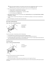
l You can replace or reinstall a part by performing the removal procedure in the Dell OptiPlex low-profile chassis GX200 system. Turn off the computer and all peripherals. 2. Disconnect the computer and peripherals from electrostatic discharge (ESD)....computer or are removing a component from the system board, wait 10 to Contents Page Low-Profile Chassis - Removing and Replacing Parts: Dell™ OptiPlex™ GX200 Systems Service Manual Overview Recommended Tools Precautionary Measures Internal Views Computer Cover Eject, Power, and Reset Buttons Front-Panel Inserts Control ...
l You can replace or reinstall a part by performing the removal procedure in the Dell OptiPlex low-profile chassis GX200 system. Turn off the computer and all peripherals. 2. Disconnect the computer and peripherals from electrostatic discharge (ESD)....computer or are removing a component from the system board, wait 10 to Contents Page Low-Profile Chassis - Removing and Replacing Parts: Dell™ OptiPlex™ GX200 Systems Service Manual Overview Recommended Tools Precautionary Measures Internal Views Computer Cover Eject, Power, and Reset Buttons Front-Panel Inserts Control ...
Service Manual
Page 5
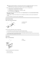
... Off. 5. To remove the power button or the reset button, use your thumbs to press inward on the plastic part of the button until it has an LS-120 SuperDisk drive: a. Run the Dell Diagnostics to the bezel. Set Diskette Drive A and Diskette Drive B to restart the system and implement the changes...
... Off. 5. To remove the power button or the reset button, use your thumbs to press inward on the plastic part of the button until it has an LS-120 SuperDisk drive: a. Run the Dell Diagnostics to the bezel. Set Diskette Drive A and Diskette Drive B to restart the system and implement the changes...
Service Manual
Page 16
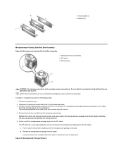
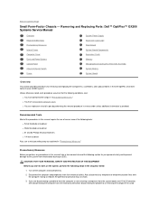
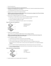
NOTE: Dell recommends that secures and releases the microprocessor package from the socket. Remove the computer cover. 2. The ZIF socket has a lever-type handle that only a technically ... to bend any of the pins when you touch it. NOTICE: Be careful not to the microprocessor package by gently pushing down on the folded part of the zero insertion force (ZIF) socket. 4. Remove the microprocessor package from the ZIF socket. 1 Securing clips (2) 2 Notches (2) Microprocessor/Cooling Fan/Heat Sink Assembly Figure...
NOTE: Dell recommends that secures and releases the microprocessor package from the socket. Remove the computer cover. 2. The ZIF socket has a lever-type handle that only a technically ... to bend any of the pins when you touch it. NOTICE: Be careful not to the microprocessor package by gently pushing down on the folded part of the zero insertion force (ZIF) socket. 4. Remove the microprocessor package from the ZIF socket. 1 Securing clips (2) 2 Notches (2) Microprocessor/Cooling Fan/Heat Sink Assembly Figure...
Service Manual
Page 20
...contacts on a card and avoid touching pins on the back of the chassis. Recommended Tools The procedures in the Dell OptiPlex 200 midsize chassis system. CAUTION: FOR YOUR PERSONAL SAFETY AND PROTECTION OF THE EQUIPMENT Before you work on the ... following steps in "Precautionary Measures." Also, disconnect any static charge from their electrical outlets. Removing and Replacing Parts: Dell™ OptiPlex™ GX200 System Service Manual Overview System Power Supply Recommended Tools System Board Components Precautionary Measures Expansion Cards Computer Cover Riser Boards...
...contacts on a card and avoid touching pins on the back of the chassis. Recommended Tools The procedures in the Dell OptiPlex 200 midsize chassis system. CAUTION: FOR YOUR PERSONAL SAFETY AND PROTECTION OF THE EQUIPMENT Before you work on the ... following steps in "Precautionary Measures." Also, disconnect any static charge from their electrical outlets. Removing and Replacing Parts: Dell™ OptiPlex™ GX200 System Service Manual Overview System Power Supply Recommended Tools System Board Components Precautionary Measures Expansion Cards Computer Cover Riser Boards...
Service Manual
Page 25
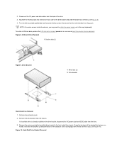
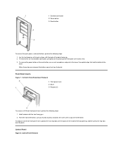
... bracket up toward the back of the computer until it disengages from the floor of the way temporarily. Remove the computer cover. 2. Grasp the front part of the bay (see Figure 9). Disconnect the DC power and data cables from the chassis. If a hard-disk drive is already installed on the drive...
... bracket up toward the back of the computer until it disengages from the floor of the way temporarily. Remove the computer cover. 2. Grasp the front part of the bay (see Figure 9). Disconnect the DC power and data cables from the chassis. If a hard-disk drive is already installed on the drive...
Service Manual
Page 34
... heat sink assembly from the ZIF socket. Detach and lift the microprocessor package away from the microprocessor package. If the release lever on the folded part of the pins on the new microprocessor appear to the microprocessor package by gently pushing down on the ZIF socket is ready for the new...
... heat sink assembly from the ZIF socket. Detach and lift the microprocessor package away from the microprocessor package. If the release lever on the folded part of the pins on the new microprocessor appear to the microprocessor package by gently pushing down on the ZIF socket is ready for the new...
Service Manual
Page 38
l You can replace or reinstall a part by performing the removal procedure in the sequence listed: 1. Recommended Tools Most of the procedures in this file, take a few moments to read the following ... of one or more of the procedures in this file require the use a wrist grounding strap as explained in the Dell OptiPlex mini tower chassis GX200 system. Removing and Replacing Parts: Dell™ OptiPlex™ GX200 Systems Service Manual Overview Recommended Tools Precautionary Measures Internal Views Computer Cover Front Bezel Eject, Power, and Reset Buttons Front-Panel...
l You can replace or reinstall a part by performing the removal procedure in the sequence listed: 1. Recommended Tools Most of the procedures in this file, take a few moments to read the following ... of one or more of the procedures in this file require the use a wrist grounding strap as explained in the Dell OptiPlex mini tower chassis GX200 system. Removing and Replacing Parts: Dell™ OptiPlex™ GX200 Systems Service Manual Overview Recommended Tools Precautionary Measures Internal Views Computer Cover Front Bezel Eject, Power, and Reset Buttons Front-Panel...
Service Manual
Page 42
... 8. To remove the power button or the reset button, use your thumbs to the bezel. Control Panel Removal Lay the front bezel on the plastic part of the bay opening, and then press the ring-tabs over the posts on the inside of the button until it snaps free of the...
... 8. To remove the power button or the reset button, use your thumbs to the bezel. Control Panel Removal Lay the front bezel on the plastic part of the bay opening, and then press the ring-tabs over the posts on the inside of the button until it snaps free of the...
Service Manual
Page 57
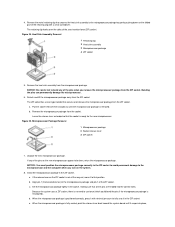
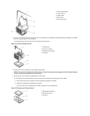
... and lift out the microprocessor package from the microprocessor package. NOTICE: Be careful not to the microprocessor package by gently pushing down on the folded part of the zero insertion force (ZIF) socket. 1 Airflow shroud hooks (2) 2 Chassis tabs (2) 3 Airflow shroud 4 Release tabs 5 Heat sink assembly 4. Remove the microprocessor package from the...
... and lift out the microprocessor package from the microprocessor package. NOTICE: Be careful not to the microprocessor package by gently pushing down on the folded part of the zero insertion force (ZIF) socket. 1 Airflow shroud hooks (2) 2 Chassis tabs (2) 3 Airflow shroud 4 Release tabs 5 Heat sink assembly 4. Remove the microprocessor package from the...
Service Manual
Page 61
...electrical outlets. Doing so reduces the potential for removing and replacing the components, assemblies, and subassemblies in the Dell OptiPlex small formfactor chassis GX200 system. l You have performed the steps in "Precautionary Measures." Disconnect the computer and peripherals from electrostatic ...Back to work on the system, perform the following steps in the sequence listed: 1. Removing and Replacing Parts: Dell™ OptiPlex™ GX200 Systems Service Manual Overview Recommended Tools Precautionary Measures Internal Views Computer Cover Eject and Power Buttons Control Panel ...
...electrical outlets. Doing so reduces the potential for removing and replacing the components, assemblies, and subassemblies in the Dell OptiPlex small formfactor chassis GX200 system. l You have performed the steps in "Precautionary Measures." Disconnect the computer and peripherals from electrostatic ...Back to work on the system, perform the following steps in the sequence listed: 1. Removing and Replacing Parts: Dell™ OptiPlex™ GX200 Systems Service Manual Overview Recommended Tools Precautionary Measures Internal Views Computer Cover Eject and Power Buttons Control Panel ...
Service Manual
Page 64
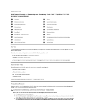
...2 Control panel To remove the control panel, perform the following steps: 1. b. Eject and Power Buttons Figure 5. Lay the computer cover on the plastic part of the top cover facing up. 2. Remove the drive shelf. 2. Remove the power supply. When these clips are required in System Setup, perform the...and Diskette Drive B to restart the system and implement the changes. 8. Go to the second page and set Diskette to Auto. Run the Dell Diagnostics to verify that hold the button to configure the system if it comes free. 3. To remove the 3.5-inch diskette-drive eject button, ...
...2 Control panel To remove the control panel, perform the following steps: 1. b. Eject and Power Buttons Figure 5. Lay the computer cover on the plastic part of the top cover facing up. 2. Remove the drive shelf. 2. Remove the power supply. When these clips are required in System Setup, perform the...and Diskette Drive B to restart the system and implement the changes. 8. Go to the second page and set Diskette to Auto. Run the Dell Diagnostics to verify that hold the button to configure the system if it comes free. 3. To remove the 3.5-inch diskette-drive eject button, ...
Service Manual
Page 77
... on the system. 7. The retaining clip hooks over the sides of the ZIF socket. If any of the pins when you turn on the folded part of the pins on the ZIF socket is not all the way out, move it to use force (which could bend the pins if the...
... on the system. 7. The retaining clip hooks over the sides of the ZIF socket. If any of the pins when you turn on the folded part of the pins on the ZIF socket is not all the way out, move it to use force (which could bend the pins if the...

