Service Manual
Page 8
... 1-20. Figure 1-27. Figure 4-11. P3, P4, P5, P6, and P9 (All OptiPlex GX1 Chassis 1-24 DC Power Connectors P2 (Low-Profile Chassis) and P7 (All OptiPlex GX1 Chassis 1-24 DC Power Cables for the Low-Profile Computer 1-25 DC Power Distribution for the Low-Profile Computer. . . ....Midsize Computer (Option 1 1-14 Riser Board for the Midsize Computer (Option 2 1-14 Riser Board for the OptiPlex NX1 Computer . . . . 1-32 Connecting an External Diskette Drive to the OptiPlex NX1 Computer 2-9 Internal View of the Low-Profile Computer 4-3 Computer Cover Removal 4-3 Eject, Power, and Reset ...
... 1-20. Figure 1-27. Figure 4-11. P3, P4, P5, P6, and P9 (All OptiPlex GX1 Chassis 1-24 DC Power Connectors P2 (Low-Profile Chassis) and P7 (All OptiPlex GX1 Chassis 1-24 DC Power Cables for the Low-Profile Computer 1-25 DC Power Distribution for the Low-Profile Computer. . . ....Midsize Computer (Option 1 1-14 Riser Board for the Midsize Computer (Option 2 1-14 Riser Board for the OptiPlex NX1 Computer . . . . 1-32 Connecting an External Diskette Drive to the OptiPlex NX1 Computer 2-9 Internal View of the Low-Profile Computer 4-3 Computer Cover Removal 4-3 Eject, Power, and Reset ...

Service Manual
Page 17
... as described in Chapter 2, "Basic Troubleshooting." The 40-pin AMC connector, shown in and microphone input. The OptiPlex NX1 system contains an integrated controller and diskette drive connector but is not equipped with 65,535 colors at 75 Hz. The SVGA subsystem consists of three ports into the graphics ... of the video stream data transfers occur on the system board, which drives an external SVGA monitor. A fourth port, audio mixing bus (AMB), is a single chip that connects to the system board, CD-ROM audio cables must be attached from the graphics controller to the device, for a ...
... as described in Chapter 2, "Basic Troubleshooting." The 40-pin AMC connector, shown in and microphone input. The OptiPlex NX1 system contains an integrated controller and diskette drive connector but is not equipped with 65,535 colors at 75 Hz. The SVGA subsystem consists of three ports into the graphics ... of the video stream data transfers occur on the system board, which drives an external SVGA monitor. A fourth port, audio mixing bus (AMB), is a single chip that connects to the system board, CD-ROM audio cables must be attached from the graphics controller to the device, for a ...

Service Manual
Page 21
power supply padlock ring voltage selection switch AC power receptacle parallel port connector serial port 1 connector mouse connector keyboard connector USB connectors (2) serial port 2 connector 3.5-inch diskette drive diskette/tape drive interface cable hard-disk drive interface cable hard-disk drive chassis intrusion switch audio connectors (3) NIC connector (optional) video connector security cable slot expansion-card cage expansion-card slots (3) System Overview 1-9
power supply padlock ring voltage selection switch AC power receptacle parallel port connector serial port 1 connector mouse connector keyboard connector USB connectors (2) serial port 2 connector 3.5-inch diskette drive diskette/tape drive interface cable hard-disk drive interface cable hard-disk drive chassis intrusion switch audio connectors (3) NIC connector (optional) video connector security cable slot expansion-card cage expansion-card slots (3) System Overview 1-9

Service Manual
Page 22
3.5-inch diskette drive diskette/tape drive interface cable drive cage power supply hard-disk drive bracket AC power receptacle voltage selection switch padlock ring chassis intrusion switch hard-disk drive interface cable parallel port connector serial port 1 connector mouse connector keyboard connector USB connectors (2) serial port 2 connector expansion-card cage expansion-card slots (5) NIC connector (optional) video connector security cable slot audio connectors (3) 1-10
3.5-inch diskette drive diskette/tape drive interface cable drive cage power supply hard-disk drive bracket AC power receptacle voltage selection switch padlock ring chassis intrusion switch hard-disk drive interface cable parallel port connector serial port 1 connector mouse connector keyboard connector USB connectors (2) serial port 2 connector expansion-card cage expansion-card slots (5) NIC connector (optional) video connector security cable slot audio connectors (3) 1-10

Service Manual
Page 23
AC power receptacle security cable slot parallel port connector serial port 1 connector keyboard connector mouse connector USB connectors (2) serial port 2 connector video connector NIC connector (optional) audio connectors (3) padlock ring power supply external drive bays hard-disk drive bracket interface cable chassis intrusion switch expansion-card cage system board riser board System Overview 1-11
AC power receptacle security cable slot parallel port connector serial port 1 connector keyboard connector mouse connector USB connectors (2) serial port 2 connector video connector NIC connector (optional) audio connectors (3) padlock ring power supply external drive bays hard-disk drive bracket interface cable chassis intrusion switch expansion-card cage system board riser board System Overview 1-11

Service Manual
Page 24
... port connector serial port 1 connector mouse connector keyboard connector USB connectors (2) serial port 2 connector hard-disk drive expansion-card cage expansion-card slot security cable slot AC power receptacle NIC connector (optional) video connector The OptiPlex GX1 systems contain advanced expansion subsystems that can be accessed by double-clicking the System icon in...
... port connector serial port 1 connector mouse connector keyboard connector USB connectors (2) serial port 2 connector hard-disk drive expansion-card cage expansion-card slot security cable slot AC power receptacle NIC connector (optional) video connector The OptiPlex GX1 systems contain advanced expansion subsystems that can be accessed by double-clicking the System icon in...
Service Manual
Page 36
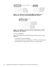
1234 P2, P3, P5, P6, P9 +5 VDC (red) common (black) common (black) +12 VDC (yellow) P4 12 34 +12 VDC (yellow) common (black) common (black) +5 VDC (red) P2, P7 1 2 34 5 6 +3.3 VDC (blue/white) +3.3 VDC (blue/white) +3.3 VDC (blue/white) common (black) common (black) common (black) Figures 1-18 through 1-22 provide the following information about DC power distribution: Power-supply connector identification Power cable connections for diskette, tape, CD-ROM, and hard-disk drives Power distribution to sockets and connectors on the system board 1-24
1234 P2, P3, P5, P6, P9 +5 VDC (red) common (black) common (black) +12 VDC (yellow) P4 12 34 +12 VDC (yellow) common (black) common (black) +5 VDC (red) P2, P7 1 2 34 5 6 +3.3 VDC (blue/white) +3.3 VDC (blue/white) +3.3 VDC (blue/white) common (black) common (black) common (black) Figures 1-18 through 1-22 provide the following information about DC power distribution: Power-supply connector identification Power cable connections for diskette, tape, CD-ROM, and hard-disk drives Power distribution to sockets and connectors on the system board 1-24

Service Manual
Page 43
P2 1 2 34 5 6 +3.3 VDC (blue/white) +3.3 VDC (blue/white) +3.3 VDC (blue/white) common (black) common (black) common (black) 1234 P3 +5 VDC (red) common (black) common (black) +12 VDC (yellow) Figures 1-26 and 1-27 provide the following information about DC power distribution: Power-supply connector identification Power cable connection for the hard-disk drive Power distribution to sockets and connectors on the system board P3 P2 P1 System Overview 1-31
P2 1 2 34 5 6 +3.3 VDC (blue/white) +3.3 VDC (blue/white) +3.3 VDC (blue/white) common (black) common (black) common (black) 1234 P3 +5 VDC (red) common (black) common (black) +12 VDC (yellow) Figures 1-26 and 1-27 provide the following information about DC power distribution: Power-supply connector identification Power cable connection for the hard-disk drive Power distribution to sockets and connectors on the system board P3 P2 P1 System Overview 1-31

Service Manual
Page 56
... indicators: These indicators light up during the boot routine, troubleshoot the diskette drive or hard-disk drive subsystem, as a loose expansion card, cable connector, or mounting screw. If either of a computer's interior hardware can indicate problems or provide status information. No. See ...light up in this chapter. Does the Diagnostics Menu appear? Yes. To perform the internal visual inspection, follow these indicators fails to or from the drives. If a system error message is a series of a problem, such as appropriate. No. Beep codes: A beep code is displayed, see ...
... indicators: These indicators light up during the boot routine, troubleshoot the diskette drive or hard-disk drive subsystem, as a loose expansion card, cable connector, or mounting screw. If either of a computer's interior hardware can indicate problems or provide status information. No. See ...light up in this chapter. Does the Diagnostics Menu appear? Yes. To perform the internal visual inspection, follow these indicators fails to or from the drives. If a system error message is a series of a problem, such as appropriate. No. Beep codes: A beep code is displayed, see ...

Service Manual
Page 61
... Ports Tests - hard-disk drive external diskette drive diskette drive connector Y-cable P3 connector interface cable Basic Troubleshooting 2-9 Verify the basic operation of the NIC, including read and write access to the computer as the hard-disk-based diagnostics. The OptiPlex NX1 systems use either server-based, hard-disk-based or optionally diskette-based diagnostics using...
... Ports Tests - hard-disk drive external diskette drive diskette drive connector Y-cable P3 connector interface cable Basic Troubleshooting 2-9 Verify the basic operation of the NIC, including read and write access to the computer as the hard-disk-based diagnostics. The OptiPlex NX1 systems use either server-based, hard-disk-based or optionally diskette-based diagnostics using...

Service Manual
Page 67
...drive. Table 3-2 lists the system error messages that must be solved before the system will reboot. Diskette drive or harddisk drive controller detected uncorrectable read error. BIOS found faulty disk sector or could not find particular disk sector. Faulty diskette/tape drive subsystem or hard-disk drive... subsystem (defective system board). Faulty diskette/tape drive subsystem or hard-disk drive subsystem (... exist or is detected by the system. Hard-disk drive or associated controller defective. Beep Codes and Error Messages ...
...drive. Table 3-2 lists the system error messages that must be solved before the system will reboot. Diskette drive or harddisk drive controller detected uncorrectable read error. BIOS found faulty disk sector or could not find particular disk sector. Faulty diskette/tape drive subsystem or hard-disk drive... subsystem (defective system board). Faulty diskette/tape drive subsystem or hard-disk drive subsystem (... exist or is detected by the system. Hard-disk drive or associated controller defective. Beep Codes and Error Messages ...

Service Manual
Page 68
... faulty or improperly seated. Faulty or improperly inserted diskette, incorrect configuration settings in System Setup program, improperly connected hard-disk drive cable, faulty hard-disk drive controller subsystem (defective system board), or loose power cable. 3-4 System could not locate specific sector or track. Diskette write-protected. Faulty keyboard controller (defective system board). Incorrect configuration...
... faulty or improperly seated. Faulty or improperly inserted diskette, incorrect configuration settings in System Setup program, improperly connected hard-disk drive cable, faulty hard-disk drive controller subsystem (defective system board), or loose power cable. 3-4 System could not locate specific sector or track. Diskette write-protected. Faulty keyboard controller (defective system board). Incorrect configuration...

Service Manual
Page 70
... particular sector on dis- Memory test did not complete. diskette. Faulty diskette, diskette/ tape drive subsystem, hard-disk drive, hard-disk drive subsystem, or no operating system on hard-disk drive. malfunctioning. Improperly connected diskette/tape drive, harddisk drive interface cable, or power cable. Diskette in System Setup program incorrect or operating system corrupted. Faulty diskette, diskette/ tape...
... particular sector on dis- Memory test did not complete. diskette. Faulty diskette, diskette/ tape drive subsystem, hard-disk drive, hard-disk drive subsystem, or no operating system on hard-disk drive. malfunctioning. Improperly connected diskette/tape drive, harddisk drive interface cable, or power cable. Diskette in System Setup program incorrect or operating system corrupted. Faulty diskette, diskette/ tape...

Service Manual
Page 79
DC power cable diskette/tape drive interface cable power supply 3.5-inch diskette drive 5.25-inch drive bay and bracket hard-disk drive DSKT connector EIDE cable secondary EIDE interface connector (IDE2) primary EIDE interface connector (IDE1) The following subsections. Figure 4-6 shows an example of the procedures in the following subsections contain removal/replacement procedures for drives installed in the...
DC power cable diskette/tape drive interface cable power supply 3.5-inch diskette drive 5.25-inch drive bay and bracket hard-disk drive DSKT connector EIDE cable secondary EIDE interface connector (IDE2) primary EIDE interface connector (IDE1) The following subsections. Figure 4-6 shows an example of the procedures in the following subsections contain removal/replacement procedures for drives installed in the...

Service Manual
Page 97
3.5-inch diskette drive diskette/tape drive interface cable power supply system board external drive bays hard-disk drive bracket hard-disk drive interface cable expansion-card cage Removing and Replacing Parts on the Midsize Chassis 5-3
3.5-inch diskette drive diskette/tape drive interface cable power supply system board external drive bays hard-disk drive bracket hard-disk drive interface cable expansion-card cage Removing and Replacing Parts on the Midsize Chassis 5-3

Service Manual
Page 103
... can be installed in the computer. system power supply DC power cable diskette/tape drive interface cable 3.5-inch diskette drive hard-disk drive bracket EIDE cable DSKT connector primary EIDE interface connector (IDE1) secondary EIDE interface connector (IDE2) The following subsections contain removal/replacement procedures for drives installed in the following subsections. Removing and Replacing Parts on...
... can be installed in the computer. system power supply DC power cable diskette/tape drive interface cable 3.5-inch diskette drive hard-disk drive bracket EIDE cable DSKT connector primary EIDE interface connector (IDE1) secondary EIDE interface connector (IDE2) The following subsections contain removal/replacement procedures for drives installed in the following subsections. Removing and Replacing Parts on...

Service Manual
Page 128
Figure 6-8 shows an example of the procedures in the computer. Refer to this figure when you perform any of drive hardware that can be installed in the following subsections contain removal/replacement procedures for drives installed in the externally accessible drive bays. 6-10 diskette/tape drive interface cable 3.5-inch diskette drive DC power cable DSKT connector secondary EIDE interface connector (IDE2) primary EIDE EIDE cable interface connector (IDE1) hard-disk drive bracket The following subsections.
Figure 6-8 shows an example of the procedures in the computer. Refer to this figure when you perform any of drive hardware that can be installed in the following subsections contain removal/replacement procedures for drives installed in the externally accessible drive bays. 6-10 diskette/tape drive interface cable 3.5-inch diskette drive DC power cable DSKT connector secondary EIDE interface connector (IDE2) primary EIDE EIDE cable interface connector (IDE1) hard-disk drive bracket The following subsections.

Service Manual
Page 152
Route the EIDE cable under the cable tabs on the bottom of the chassis. systemboard DC power cables (2) power supply EIDE cable power-supply retention tab hard-disk drive DC power cable chassis tabs (2) cable tabs (2) screw AC power receptacle To remove the system power supply, follow these steps: When you reinstall the system power supply, place it in front of the two tabs on the power supply before reinstalling the expansioncard cage. 7-8 Then rotate the power supply toward the front of the chassis until the retention tab snaps into place.
Route the EIDE cable under the cable tabs on the bottom of the chassis. systemboard DC power cables (2) power supply EIDE cable power-supply retention tab hard-disk drive DC power cable chassis tabs (2) cable tabs (2) screw AC power receptacle To remove the system power supply, follow these steps: When you reinstall the system power supply, place it in front of the two tabs on the power supply before reinstalling the expansioncard cage. 7-8 Then rotate the power supply toward the front of the chassis until the retention tab snaps into place.

Service Manual
Page 153
Press gently downward on the back-right corner of the chassis to remove or install the hard-disk drive, an expansion card, or the riser board. expansion-card cage EIDE cable DC power cable securing lever slots (2) tabs (2) To remove the expansion-card cage, follow these steps: To replace an ...-card cage contains the hard-disk drive, the riser board, and any installed expansion card. The computer has a removable expansion-card cage. You must remove the expansion-card cage to ensure that the two cage slots engage the tabs on the OptiPlex NX1 Net PC Chassis 7-9 Removing and...
Press gently downward on the back-right corner of the chassis to remove or install the hard-disk drive, an expansion card, or the riser board. expansion-card cage EIDE cable DC power cable securing lever slots (2) tabs (2) To remove the expansion-card cage, follow these steps: To replace an ...-card cage contains the hard-disk drive, the riser board, and any installed expansion card. The computer has a removable expansion-card cage. You must remove the expansion-card cage to ensure that the two cage slots engage the tabs on the OptiPlex NX1 Net PC Chassis 7-9 Removing and...

Service Manual
Page 171
... supply, 1-7 ATI multimedia channel, 1-5 audio connectors, 1-7 controller, 1-5 battery removal low-profile computer, 4-20 midsize computer, 5-23 mini tower computer, 6-25 OptiPlex NX1 computer, 7-17 beep codes, 3-1 BIOS, flash ROM, 1-4 cabling, verification, 2-2 CD-ROM drives removal, low-profile computer, 4-9 removal, midsize computer, 5-11 removal, mini tower computer, 6-12 chassis configurations, 1-2 differences, 1-2 intrusion detection, 1-6 similarities...
... supply, 1-7 ATI multimedia channel, 1-5 audio connectors, 1-7 controller, 1-5 battery removal low-profile computer, 4-20 midsize computer, 5-23 mini tower computer, 6-25 OptiPlex NX1 computer, 7-17 beep codes, 3-1 BIOS, flash ROM, 1-4 cabling, verification, 2-2 CD-ROM drives removal, low-profile computer, 4-9 removal, midsize computer, 5-11 removal, mini tower computer, 6-12 chassis configurations, 1-2 differences, 1-2 intrusion detection, 1-6 similarities...


