User Guide
Page 3
... and off when you have not resolved the problem, continue with video during POST indicate that the power supply may be caused by the application program you have a power indicator (usually on getting technical assistance from Dell. Make sure that the microprocessor is not caused by a hardware malfunction. Look and listen for instructions on...
... and off when you have not resolved the problem, continue with video during POST indicate that the power supply may be caused by the application program you have a power indicator (usually on getting technical assistance from Dell. Make sure that the microprocessor is not caused by a hardware malfunction. Look and listen for instructions on...
User Guide
Page 23
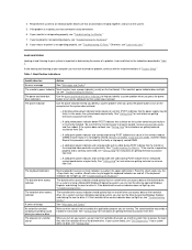
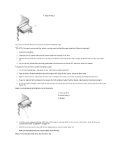
Remove the computer cover as instructed in the bay and you are replacing it, disconnect the DC power cable and interface cable from the back of the drive before you slide the bracket out of the drive (see Figure 11). Figure 9. To ensure ... the bracket, turn the drive/bracket assembly upside down and unscrew the four screws that extend from the bay you may want to rotate the power supply out of the drive up so that the tabs on the front of the bay (see Figure 10). 5. c. Figure 10. Remove the front bezel (mini...
Remove the computer cover as instructed in the bay and you are replacing it, disconnect the DC power cable and interface cable from the back of the drive before you slide the bracket out of the drive (see Figure 11). Figure 9. To ensure ... the bracket, turn the drive/bracket assembly upside down and unscrew the four screws that extend from the bay you may want to rotate the power supply out of the drive up so that the tabs on the front of the bay (see Figure 10). 5. c. Figure 10. Remove the front bezel (mini...
User Guide
Page 48
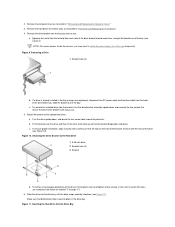
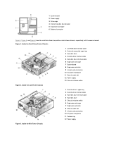
Back to Contents Page Inside Your Computer: Dell™ OptiPlex™ GX100 System User's Guide Overview Internal Views System Board Components System Board Jumpers System Board Labels Rotating the Power Supply Away From the System Board (Mini Tower Chassis Only) Removing and Replacing the Front Bezel (Mini Tower Chassis Only) Removing and ... Before you perform an upgrade procedure. Small-Form-Factor Chassis Orientation View 1 System board 2 Diskette drive 3 Hard-disk drive 4 CD-ROM drive 5 Power supply Figure 2. Low-Profile Chassis Orientation View 1 System board 2 Hard-disk drive...
Back to Contents Page Inside Your Computer: Dell™ OptiPlex™ GX100 System User's Guide Overview Internal Views System Board Components System Board Jumpers System Board Labels Rotating the Power Supply Away From the System Board (Mini Tower Chassis Only) Removing and Replacing the Front Bezel (Mini Tower Chassis Only) Removing and ... Before you perform an upgrade procedure. Small-Form-Factor Chassis Orientation View 1 System board 2 Diskette drive 3 Hard-disk drive 4 CD-ROM drive 5 Power supply Figure 2. Low-Profile Chassis Orientation View 1 System board 2 Hard-disk drive...
User Guide
Page 49
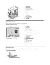
...Chassis intrusion switch 6 Expansion-card cage 7 Expansion-card slots 8 Security cable slot 9 I /O ports and connectors 10 AC power receptacle 11 Security cable slot 12 Power supply 13 Chassis intrusion switch Figure 5. Figure 4. 1 System board 2 Power supply 3 Drive cage 4 Internal hard-disk drive bracket 5 Expansion-card cage 6 Bottom of computer Figure 4, Figure 5, and ... Diskette-drive interface cable 5 Hard-disk drive interface cable 6 Expansion-card cage 7 System board 8 Expansion-card slots 9 I /O ports and connectors 10 AC power receptacle 11 Padlock ring 12 Power supply Figure 6.
...Chassis intrusion switch 6 Expansion-card cage 7 Expansion-card slots 8 Security cable slot 9 I /O ports and connectors 10 AC power receptacle 11 Security cable slot 12 Power supply 13 Chassis intrusion switch Figure 5. Figure 4. 1 System board 2 Power supply 3 Drive cage 4 Internal hard-disk drive bracket 5 Expansion-card cage 6 Bottom of computer Figure 4, Figure 5, and ... Diskette-drive interface cable 5 Hard-disk drive interface cable 6 Expansion-card cage 7 System board 8 Expansion-card slots 9 I /O ports and connectors 10 AC power receptacle 11 Padlock ring 12 Power supply Figure 6.
User Guide
Page 50
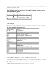
...5 Expansion-card cage 6 System board 7 Riser board 8 Padlock ring 9 Security cable slot 10 I/O ports and connectors 11 AC power receptacle 12 Power supply System Board Components Figure 7 shows the system board and the location of jumpers on the system board. System Board Jumpers Figure 8. ... connector 10 IDE1 connector 11 IDE2 connector 12 Diskette/tape-drive connector 13 Battery 14 Auxiliary power indicator 15 DIMM connectors (2) 16 Control panel connector 17 3.3-V power connector 18 DC power connector System Board Jumpers Figure 8 shows the layout of all its sockets and connectors.
...5 Expansion-card cage 6 System board 7 Riser board 8 Padlock ring 9 Security cable slot 10 I/O ports and connectors 11 AC power receptacle 12 Power supply System Board Components Figure 7 shows the system board and the location of jumpers on the system board. System Board Jumpers Figure 8. ... connector 10 IDE1 connector 11 IDE2 connector 12 Diskette/tape-drive connector 13 Battery 14 Auxiliary power indicator 15 DIMM connectors (2) 16 Control panel connector 17 3.3-V power connector 18 DC power connector System Board Jumpers Figure 8 shows the layout of all its sockets and connectors.
User Guide
Page 51
.... CAUTION: Before you may occur. NOTICE: Make sure your system or unpredictable results may have to rotate the mini tower chassis system power supply out of their functions. Jumpers are disabled. The wire connects the pins and creates a circuit. To change a jumper setting, pull ...a brief description of the way. Remove the computer cover as LPT1 Main power input connector 3.3-volt (V) power input connector Riser board connector Serial port connectors Universal Serial Bus (USB) connectors Rotating the Power Supply Away From the System Board (Mini Tower Chassis Only) To access some ...
.... CAUTION: Before you may occur. NOTICE: Make sure your system or unpredictable results may have to rotate the mini tower chassis system power supply out of their functions. Jumpers are disabled. The wire connects the pins and creates a circuit. To change a jumper setting, pull ...a brief description of the way. Remove the computer cover as LPT1 Main power input connector 3.3-volt (V) power input connector Riser board connector Serial port connectors Universal Serial Bus (USB) connectors Rotating the Power Supply Away From the System Board (Mini Tower Chassis Only) To access some ...
User Guide
Page 52
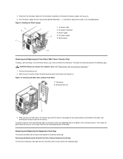
...and Replacing the Small-Form-Factor Chassis Expansion-Card Cage To remove the expansion-card cage from the AC power receptacle on the bezel. Free the power supply from the securing tab labeled "RELEASE ->," and rotate it upward until the tabs snap into their corresponding ... fit the two retaining hooks on the bezel into their corresponding slots at the bottom of the power supply (see Figure 9). 3. Rotating the Power Supply 1 AC power cable 2 AC power receptacle 3 Power supply 4 DC power cables 5 Securing tab Removing and Replacing the Front Bezel (Mini Tower Chassis Only) To access ...
...and Replacing the Small-Form-Factor Chassis Expansion-Card Cage To remove the expansion-card cage from the AC power receptacle on the bezel. Free the power supply from the securing tab labeled "RELEASE ->," and rotate it upward until the tabs snap into their corresponding ... fit the two retaining hooks on the bezel into their corresponding slots at the bottom of the power supply (see Figure 9). 3. Rotating the Power Supply 1 AC power cable 2 AC power receptacle 3 Power supply 4 DC power cables 5 Securing tab Removing and Replacing the Front Bezel (Mini Tower Chassis Only) To access ...
User Guide
Page 63
... video subsystem. Also, disconnect any necessary changes, and reboot the system. 2. Also verify that the power cables from the power supply are firmly connected to indicate a drive problem during execution of either the boot routine or the Dell Diagnostics, or if a drive is the source of the problem. Run the appropriate test group for...
... video subsystem. Also, disconnect any necessary changes, and reboot the system. 2. Also verify that the power cables from the power supply are firmly connected to indicate a drive problem during execution of either the boot routine or the Dell Diagnostics, or if a drive is the source of the problem. Run the appropriate test group for...
User Guide
Page 71
Remove the computer cover, rotate the power supply, and check the installed DIMMs to verify that they are operating properly. Run the Dell Diagnostics to make sure that the DIMMs are seated properly in their electrical outlets. If the memory total is correct, skip to Enabled or Enabled-...
Remove the computer cover, rotate the power supply, and check the installed DIMMs to verify that they are operating properly. Run the Dell Diagnostics to make sure that the DIMMs are seated properly in their electrical outlets. If the memory total is correct, skip to Enabled or Enabled-...
User Guide
Page 76
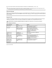
... see "Getting Help" for instructions on obtaining technical assistance. CAUTION: Before servicing any components inside your Diagnostics Checklist found in the Dell Diagnostics, an error message may be faulty or is incorrectly installed. Be sure that each microprocessor is correctly connected, see "Getting ... Code Blinking yellow Solid yellow Solid green and a beep code during POST Solid green power indicator and no beep code and no video during POST Cause System power supply failure. data. Record the message on the front of your computer, see "Getting Help" for instructions ...
... see "Getting Help" for instructions on obtaining technical assistance. CAUTION: Before servicing any components inside your Diagnostics Checklist found in the Dell Diagnostics, an error message may be faulty or is incorrectly installed. Be sure that each microprocessor is correctly connected, see "Getting ... Code Blinking yellow Solid yellow Solid green and a beep code during POST Solid green power indicator and no beep code and no video during POST Cause System power supply failure. data. Record the message on the front of your computer, see "Getting Help" for instructions ...
User Guide
Page 77
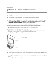
...power supply. Lift the cooling fan from the chassis hooks, and lift the shroud out of the way. Pull up and away from the microprocessor/heat sink assembly. Then remove the two thumbscrews securing the cooling fan to Contents Page Microprocessor: Dell™ OptiPlex™ GX100... System User's Guide Upgrading the Microprocessor Upgrading the Microprocessor NOTE: Dell recommends that only a technically knowledgeable person perform this procedure. CAUTION: To ...
...power supply. Lift the cooling fan from the chassis hooks, and lift the shroud out of the way. Pull up and away from the microprocessor/heat sink assembly. Then remove the two thumbscrews securing the cooling fan to Contents Page Microprocessor: Dell™ OptiPlex™ GX100... System User's Guide Upgrading the Microprocessor Upgrading the Microprocessor NOTE: Dell recommends that only a technically knowledgeable person perform this procedure. CAUTION: To ...

User Guide
Page 80
... and between the fan and the power supply bracket on using System Setup, see "System Setup." 18. c. Replace the computer cover, and then reconnect your network administrator for instructions. NOTE: For instructions on the right. Run the Dell Diagnostics to its system board connector.... 14. Replace or rotate the power supply back into position, making sure that the securing tab snaps into the alignment slot on ...
... and between the fan and the power supply bracket on using System Setup, see "System Setup." 18. c. Replace the computer cover, and then reconnect your network administrator for instructions. NOTE: For instructions on the right. Run the Dell Diagnostics to its system board connector.... 14. Replace or rotate the power supply back into position, making sure that the securing tab snaps into the alignment slot on ...
User Guide
Page 101
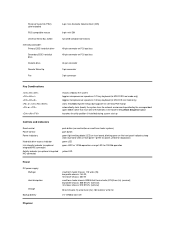
...System Setup Boot Sequence option launches the utility partition (if installed) during system start-up Controls and Indicators Reset control Power control Power indicators Hard-disk drive access indicator Link integrity indicator (on optional integrated NIC connector) Activity indicator (on optional integrated ...systems) push button green light-emitting diode (LED) on front panel-green for power, yellow for diagnostics green LED green LED for 100-Mb operation yellow LED Power DC power supply: Wattage Heat dissipation Voltage Backup battery small-form-factor chassis: 110 watts (W); blinking...
...System Setup Boot Sequence option launches the utility partition (if installed) during system start-up Controls and Indicators Reset control Power control Power indicators Hard-disk drive access indicator Link integrity indicator (on optional integrated NIC connector) Activity indicator (on optional integrated ...systems) push button green light-emitting diode (LED) on front panel-green for power, yellow for diagnostics green LED green LED for 100-Mb operation yellow LED Power DC power supply: Wattage Heat dissipation Voltage Backup battery small-form-factor chassis: 110 watts (W); blinking...
Service Manual
Page 2
... you perform any telephone or telecommunication lines from their AC power sources. Disconnect the computer and peripherals from the computer. Removing and Replacing Parts: Dell™ OptiPlex™ GX100 Systems Service Manual Overview Precautionary Measures Computer Cover Front-Panel Inserts Chassis Intrusion Switch System Power Supply System Board Components Expansion Cards Microprocessor/Heat Sink Assembly System...
... you perform any telephone or telecommunication lines from their AC power sources. Disconnect the computer and peripherals from the computer. Removing and Replacing Parts: Dell™ OptiPlex™ GX100 Systems Service Manual Overview Precautionary Measures Computer Cover Front-Panel Inserts Chassis Intrusion Switch System Power Supply System Board Components Expansion Cards Microprocessor/Heat Sink Assembly System...

Service Manual
Page 3
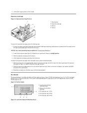
...5 Chassis intrusion switch 6 Expansion-card cage 7 Expansion-card slots 8 Security cable slot 9 I/O ports and connectors 10 AC power receptacle 11 Padlock ring 12 Power supply If it to help you orient yourself when you work inside the computer. Low-Profile Chassis Orientation View 1 System board 2 ...Hard-disk drive 3 Power supply 4 Externally accessible drive bays Figure 2 shows the low-profile chassis with the cover removed. 3. Wear a wrist grounding strap, and...
...5 Chassis intrusion switch 6 Expansion-card cage 7 Expansion-card slots 8 Security cable slot 9 I/O ports and connectors 10 AC power receptacle 11 Padlock ring 12 Power supply If it to help you orient yourself when you work inside the computer. Low-Profile Chassis Orientation View 1 System board 2 ...Hard-disk drive 3 Power supply 4 Externally accessible drive bays Figure 2 shows the low-profile chassis with the cover removed. 3. Wear a wrist grounding strap, and...

Service Manual
Page 9
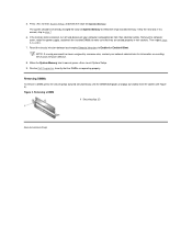
... drive by running the Dell Diagnostics (see "System Board Components." 11. If the drive you proceed to the next step. Disconnect the DC power cables from being pinched or crimped. 3. Slide the power supply toward the front of the power supply. 2. Partition and logically...User's Guide for complete information). 15. See the documentation for your operating system. Power Supply Removal 1 AC power cord 2 AC power receptacle 3 Power supply 4 DC power cables 5 Securing screw To remove the system power supply, perform the following steps: 1. Remove the screw below the fan guard on ...
... drive by running the Dell Diagnostics (see "System Board Components." 11. If the drive you proceed to the next step. Disconnect the DC power cables from being pinched or crimped. 3. Slide the power supply toward the front of the power supply. 2. Partition and logically...User's Guide for complete information). 15. See the documentation for your operating system. Power Supply Removal 1 AC power cord 2 AC power receptacle 3 Power supply 4 DC power cables 5 Securing screw To remove the system power supply, perform the following steps: 1. Remove the screw below the fan guard on ...
Service Manual
Page 10
... the tabs in the RISER connector on the system board. 3. The PCI riser board provides three PCI expansion card slots. Lift the power supply up and away from the chassis. Examine any cables connected to where the cage must be placed upon removal from the chassis. PCI ...Riser Board 1 Auxiliary power indicator LED (AUX_LED) 2 Wakeup On LAN (WOL) connector 3 PCI expansion slot 1 (PCI1) 4 PCI expansion slot 2 (PCI2) 5 PCI expansion slot 3 (PCI3) ...
... the tabs in the RISER connector on the system board. 3. The PCI riser board provides three PCI expansion card slots. Lift the power supply up and away from the chassis. Examine any cables connected to where the cage must be placed upon removal from the chassis. PCI ...Riser Board 1 Auxiliary power indicator LED (AUX_LED) 2 Wakeup On LAN (WOL) connector 3 PCI expansion slot 1 (PCI1) 4 PCI expansion slot 2 (PCI2) 5 PCI expansion slot 3 (PCI3) ...
Service Manual
Page 19
... "Precautionary Measures." Removing and Replacing Parts: Dell™ OptiPlex™ GX100 Systems Service Manual Overview Precautionary Measures Computer Cover Eject, Power, and Reset Buttons Control Panel Drives Riser Boards Expansion-Card Cage DIMMs System Battery Recommended Tools Internal Views Front Bezel Front-Panel Inserts Chassis Intrusion Switch System Power Supply System Board Components Expansion Cards Microprocessor...
... "Precautionary Measures." Removing and Replacing Parts: Dell™ OptiPlex™ GX100 Systems Service Manual Overview Precautionary Measures Computer Cover Eject, Power, and Reset Buttons Control Panel Drives Riser Boards Expansion-Card Cage DIMMs System Battery Recommended Tools Internal Views Front Bezel Front-Panel Inserts Chassis Intrusion Switch System Power Supply System Board Components Expansion Cards Microprocessor...

Service Manual
Page 20
...components. While you may need to wait 10 to 30 seconds for it to an unpainted metal surface, such as the power supply, to 20 seconds after disconnecting the computer from your body before disconnecting the peripheral or removing the component to avoid possible...cage 6 System board 7 Riser board 8 Padlock ring 9 I/O ports and connectors 10 Security cable slot 11 AC power receptacle 12 Power supply Computer Cover Figure 3. Mini Tower Chassis Orientation View 1 System board 2 Power supply 3 5.25-inch drive slots 4 Internal hard-disk drive bracket 5 Expansion-card cage 6 Bottom of Figure 24...
...components. While you may need to wait 10 to 30 seconds for it to an unpainted metal surface, such as the power supply, to 20 seconds after disconnecting the computer from your body before disconnecting the peripheral or removing the component to avoid possible...cage 6 System board 7 Riser board 8 Padlock ring 9 I/O ports and connectors 10 Security cable slot 11 AC power receptacle 12 Power supply Computer Cover Figure 3. Mini Tower Chassis Orientation View 1 System board 2 Power supply 3 5.25-inch drive slots 4 Internal hard-disk drive bracket 5 Expansion-card cage 6 Bottom of Figure 24...
Service Manual
Page 26
... the drive bay until the drive snaps securely into place in the drive bay. Inserting the New Drive Into the Drive Bay Disconnect the DC power cable and the interface cable from the back of the way temporarily. 1. Figure 13. To ensure proper installation, align all four screws in the order... on the bracket, and tighten the screws in the bracket, insert and tighten all screw holes and ensure that secure the drive to rotate the power supply out of the drive. 3. Make sure that extend from each other, and pull the bracket out of the bay (see Figure 13). Figure 14. NOTE...
... the drive bay until the drive snaps securely into place in the drive bay. Inserting the New Drive Into the Drive Bay Disconnect the DC power cable and the interface cable from the back of the way temporarily. 1. Figure 13. To ensure proper installation, align all four screws in the order... on the bracket, and tighten the screws in the bracket, insert and tighten all screw holes and ensure that secure the drive to rotate the power supply out of the drive. 3. Make sure that extend from each other, and pull the bracket out of the bay (see Figure 13). Figure 14. NOTE...


